Method for co-channel interference identification and mitigation

a co-channel interference and detection method technology, applied in the field of digital signal information demodulation, can solve the problems of reducing the bit error rate (ber) associated with the reception of the desired signal, cci signals may degrade the bit error rate (ber) of the desired signal by orders of magnitude, and multipath-induced intersymbol interference (isi) in frequency selective fading channels constitutes another major source of degradation

Active Publication Date: 2006-03-07
TRELLIS WARE TECH
View PDF21 Cites 19 Cited by
  • Summary
  • Abstract
  • Description
  • Claims
  • Application Information

AI Technical Summary

Problems solved by technology

This capacity is limited by frequency reuse, which is related to a receiver's ability to tolerate Co-Channel Interference (CCI), especially with cell splitting and cell reduction as in Personal Communication Service (PCS) systems.
The presence of CCI signals may degrade the Bit Error Rate (BER) associated with reception of the desired signal by orders of magnitude, even when the CCI power is significantly below that of the IU.
Furthermore, multipath-induced Intersymbol Interference (ISI) in frequency selective fading channels constitutes another major source of degradation.
The applicability of these techniques, however, is constrained by the number of antenna elements.
Similarly, there are user / CCI geometries for which linear combining techniques necessarily fail (e.g., when an interferer and the IU signals lie in regions where a linear combiner has equal gain).
However, they are prone to severe performance degradation when there is little or no separation.
However, since the memoryless model breaks down in systems with a transmission bandwidth larger than the coherence bandwidth of the channel, the receiver fails to provide significant mitigation of co-channel interference and totally fails to provide any mitigation of intersymbol interference.

Method used


Image

  • Method for co-channel interference identification and mitigation
  • Method for co-channel interference identification and mitigation
  • Method for co-channel interference identification and mitigation

Examples


Embodiment Construction

Signal Model and Front-end Processing

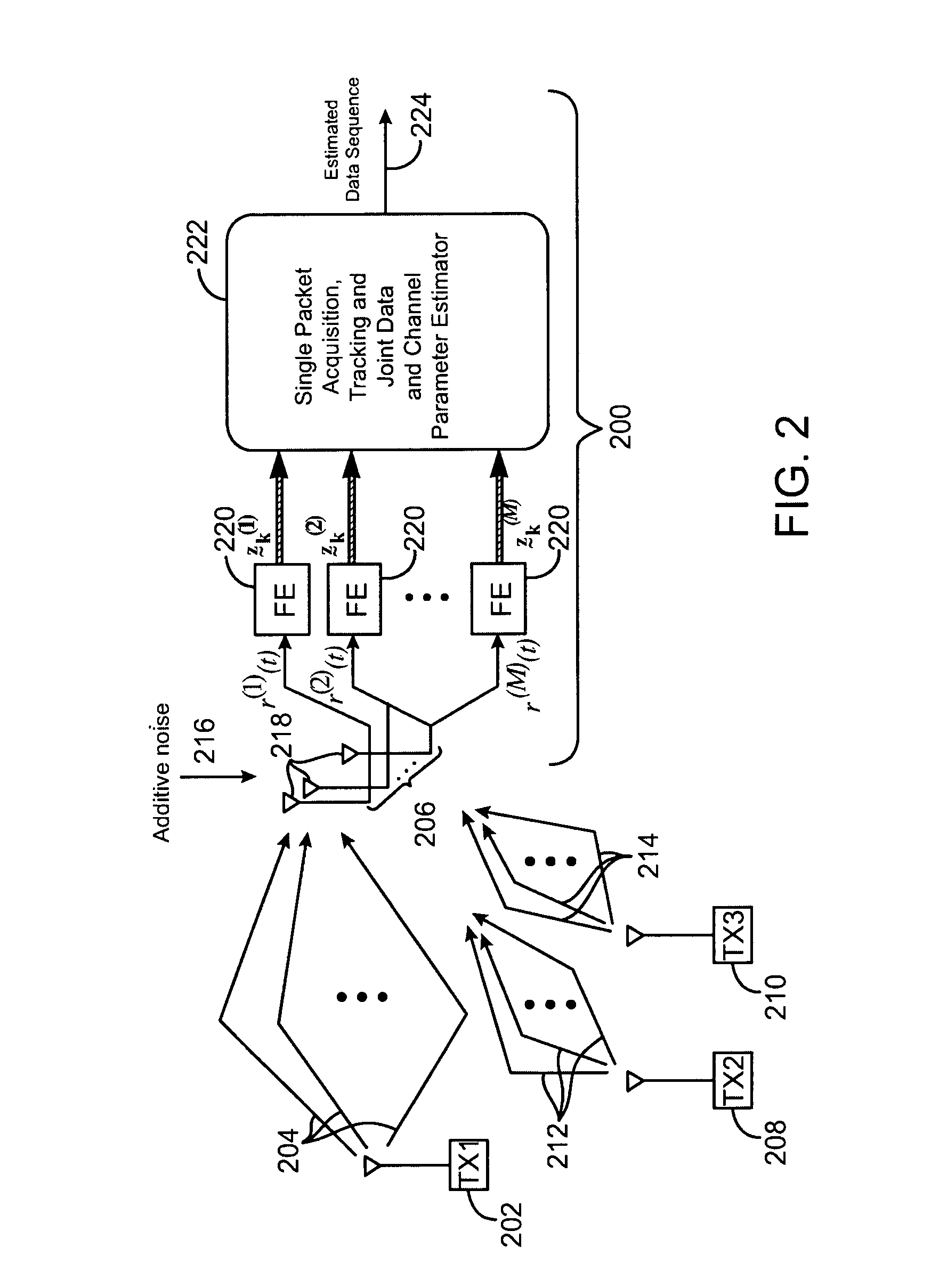
[0030]FIG. 2 is a block diagram of a receiver 200 and channel model in accordance with the invention. An Intended User (IU) 202 transmits a desired signal that is to be received by the receiver 200. The desired signal propagates along multiple paths 204 before reaching an antenna array 206 of the receiver 200. At the same time, Co-channel Interference (CCI) users 208 and 210 transmit CCI signals using the same RF frequency band as the desired signal. The CCI signals from the CCI users 208 and 210 propagate along multiple paths 212 and 214, respectively, before reaching the antenna array 206. The CCI users may be from the same cell as the IU or may be from other cells. The antenna array 206 receives additive noise 216. Thus, the combined signal received at the antenna array 206 contains a multi-path desired signal, multi-path CCI signals, and additive noise from the channel.

[0031]The antenna array 206 includes individual antenna array elements 218...


PUM


Abstract

A method for co-channel interference identification and mitigation employs adaptive sequence detection in connection with a model composed of a signal of interest and a combination of other signals which constitute interference in a channel of interest, wherein the signal of interest is distinguished from the interference by adaptive tracking of signal parameters of all identifiable signals. In a particular embodiment, the process involves estimating the number and time spans of co-channel interference channels based on maximum likelihood estimation and minimum description length from training information derived from a single time division multiple access packet; and then applying the estimate to mitigation of co-channel interference at a receiver. Per-survivor-processing is one technique for adaptive sequence detection.

Description

CROSS REFERENCES TO RELATED APPLICATIONS[0001]This invention is a non-provisional application of U.S. Provisional Application No. 60 / 251,254 filed Dec. 4, 2000, the content of which is incorporated herein by reference.STATEMENT AS TO RIGHTS TO INVENTIONS MADE UNDER FEDERALLY SPONSORED RESEARCH OR DEVELOPMENT[0002]This invention was made under partial sponsorship of U.S. Army CECOM under Contract No. DAA H07-98-C-J403. The U.S. Government retains some rights to this invention.REFERENCE TO A “SEQUENCE LISTING,” A TABLE, OR A COMPUTER PROGRAM LISTING APPENDIX SUBMITTED ON A COMPACT DISK[0003]Not ApplicableBACKGROUND OF THE INVENTION[0004]This invention relates to digital signal information demodulation and more particularly this invention relates to demodulation of packet-based wireless signals in the presence of interference from one or more of a known class of packet-based signals. Current narrowband Time Division Multiple Access (TDMA) cellular systems, such as IS-54 or GSM, are des...

Claims


Application Information

Patent Timeline
Patent Type & Authority Patents(United States)
IPC IPC(8): H03D1/04H03D1/06H03K5/01H03K6/04H04B7/10H04L25/03
CPCH04L25/03305H04L25/03331
Inventor CHUGG, KEITH M.PAPARISTO, GENTPANAGIOTOU, PROKOPIOS
Owner TRELLIS WARE TECH
Why Eureka
Try Eureka