Resonant response matching circuit for hearing aid

a technology of resonance response and hearing aid, applied in the field of circuit and method of processing audio frequency signals, to achieve the effect of convenient adjustmen

Inactive Publication Date: 2006-03-07
STARKEY LAB INC
View PDF37 Cites 18 Cited by
  • Summary
  • Abstract
  • Description
  • Claims
  • Application Information

AI Technical Summary

Benefits of technology

[0008]The present invention overcomes the disadvantages of the prior art by providing a technique for utilizing the power saving characteristics of a class D output stage within a system which has sufficient adjustability in frequency response peak gain frequency to accommodate various differences in patient-to-patient middle ear pathology. Specifically, the present invention employs an active low-pass filter which has adjustable overshoot. This filter is coupled through a buffering stage to the class D output amplifier. By adjusting the degree of overshoot, the level of the peak in the frequency response of the entire system is readily adjustable within a given therapeutic range even though the class D output amplifier is inherently difficult to tune.

Problems solved by technology

By adjusting the degree of overshoot, the level of the peak in the frequency response of the entire system is readily adjustable within a given therapeutic range even though the class D output amplifier is inherently difficult to tune.

Method used


Image

  • Resonant response matching circuit for hearing aid
  • Resonant response matching circuit for hearing aid
  • Resonant response matching circuit for hearing aid

Examples


Embodiment Construction

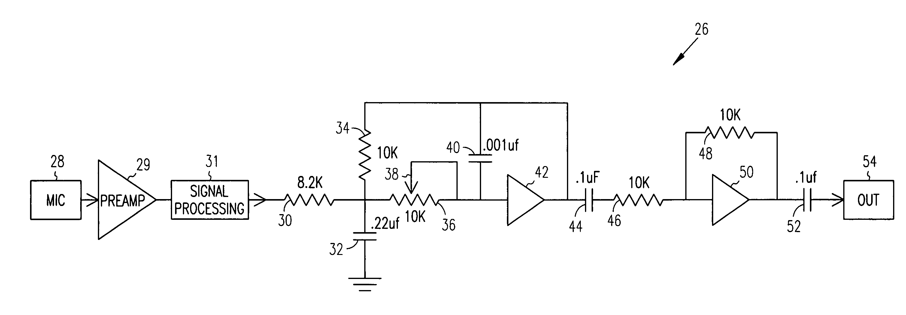
[0018]The present invention is described in accordance with several preferred embodiments which are to be viewed as illustrative without being limiting. In the preferred mode, the present invention is employed as a totally within the ear hearing aid system having a class D output stage.

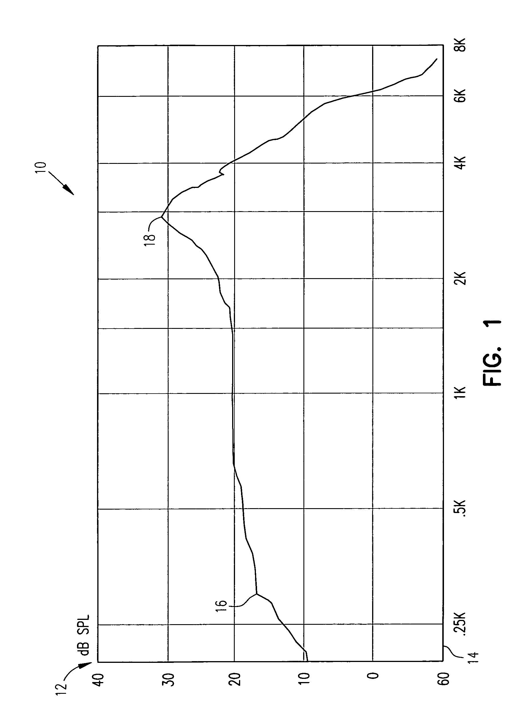
[0019]FIG. 1 is diagram 10 showing the 2 cc coupler frequency response of a typical ITE hearing aid with a class D output stage in the hearing aid receiver. Abscissa 14 is a logarithmic plot of frequency in kilohertz. Ordinate 12 shows the gain at each frequency plotted in decibels.

[0020]In a patient having normal middle ear physiology, the ear canal can be thought of as an open organ pipe having a primary resonance at about 2.8 kilohertz and a relatively flat response from about 300 hertz to about 3 kilohertz. As shown in diagram 10, gain curve 16 for the hearing aid is deliberately designed to match this response to replace the peak in gain lost when the ear canal is occluded by an ear mold. Gain pe...


PUM


Abstract

An apparatus for and method of employing an electronic hearing aid device to assist a hearing impaired patient. The resonance curve of the outer auditory canal of the patient is determined. A device in accordance with the present invention is tuned to a frequency response curve which matches the measured resonance curve. The device is tuned by adjusting the overshoot of a low pass filter stage which is interposed between the microphone input and a class D output stage.

Description

BACKGROUND OF THE INVENTION[0001]1. Field of the Invention[0002]The present invention relates generally to a circuit for and method of processing an audio frequency signal and more particularly relates to hearing aid signal processing.[0003]2. Description of the Prior Art[0004]It is well known in the art to utilize electronic devices to assist the hearing impaired. The earliest such instruments consisted of a microphone coupled to an electronic amplifier which was in turn coupled to an earphone. Quite apart from the technical difficulties experienced, these early hearing aids were sufficiently large and intrusive that the hearing impaired could be readily identified providing a degree of self-consciousness.[0005]The coming of electronic miniaturization and sub-miniaturization permitted the manufacture of hearing aid systems which are totally inserted in the outer auditory canal during use. The resulting systems provide substantially greater hearing assistance along with a much more ...

Claims


Application Information

Patent Timeline
Patent Type & Authority Patents(United States)
IPC IPC(8): H04R25/00
CPCH04R25/502H04R25/453
Inventor ROBERTS, RANDALL W.PREVES, DAVID A.BREN, MARK A.
Owner STARKEY LAB INC
Why Eureka
Try Eureka