Image coding device and method

a coding device and image technology, applied in the field of image coding methods and devices, can solve the problems of inability to carry out delicate optimal control with respect to each block, data cannot be decoded correctly, etc., and achieve the effect of suppressing the increase in the amount of generated codes and high precision

Inactive Publication Date: 2006-03-07
GK BRIDGE 1
View PDF1 Cites 10 Cited by
  • Summary
  • Abstract
  • Description
  • Claims
  • Application Information

AI Technical Summary

Benefits of technology

[0007]A first aspect of the present invention is an image coding device that encodes an image by dividing the image into units of blocks. The image coding device includes: a feature detecting means that detects features of the image as to each block; a classification means that classifies each block into one of a plurality of categories according to a result of the detection by the feature detection means; a calculation means that performs a predetermined calculation and outputs a result of the calculation, the result being a real number; and a rounding means that adds a rounding coefficient R (R≧0) to the result of the calculation that is the real number, and rounds an addition result to an integer by discarding digits to the right of the decimal point. In the image coding device, the rounding means varies a value of the rounding coefficient R according to the category into which the classification means classifies the block. By controlling the rounding means as to each block, the rounding-off is carried out with respect to a block as a unit with a great significance so that the coding with high precision can be achieved, whereas the rounding-down is carried our with respect to a block with a small significance so that a signal level is rounded down to a low level, whereby an increase in the amount of generated codes can be suppressed. Thus, the weighting of blocks with respect to the amount of the generated codes is implemented.

Problems solved by technology

However, in the case where coding parameters such as quantization steps are varied according to the blocks, a problem arises in that data cannot be decoded correctly unless information on coding parameters used when the data are compressed is included in the compressed data when the compressed data are recorded or transmitted.
This makes it impossible to carry out a delicate optimal control with respect to each block, which has been considered as a problem.

Method used


Image

  • Image coding device and method
  • Image coding device and method
  • Image coding device and method

Examples


first embodiment

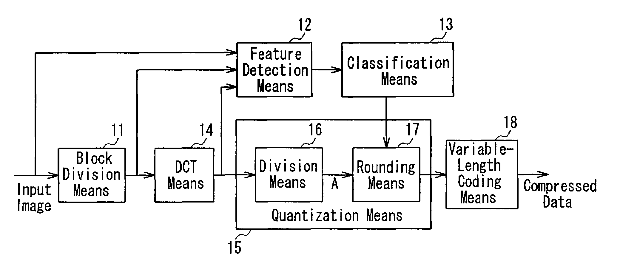
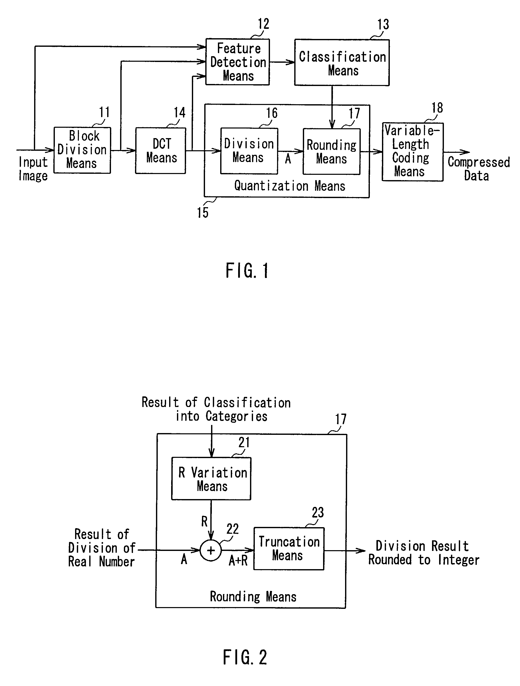
[0019]FIG. 1 is a block diagram illustrating a configuration of an image coding device according to the present embodiment, which is described referring to a case in which the present invention is applied in a DCT (discrete cosine transform) coding method such as the MPEG or the JPEG.

[0020]In FIG. 1, 11 denotes a block division means that divides an image into blocks. 12 denotes a feature detection means that detects features of an image of each block by employing an input image, an image of the block, a DCT coefficient, and the like. 13 denotes a classification means that classifies the block into one of several categories according to the significance of the block based on a result of the detection by the feature detection means 12. 14 denotes a DCT means that applies DCT to data supplied from the block division means 11. 15 denotes a quantization means that divides a DCT coefficient by a predetermined value and makes the DCT coefficient to be represented in an integer form. 16 de...

second embodiment

[0029]The following will describe, as the present embodiment, a method for detecting feature of blocks by taking advantage of a human visual characteristic with respect to a brightness level. Since an image coding device of the present embodiment has the same configuration as that in the first embodiment, the following description of the present embodiment will focus on the operations of the feature detection means 12 that detects features of blocks and the classification means 13.

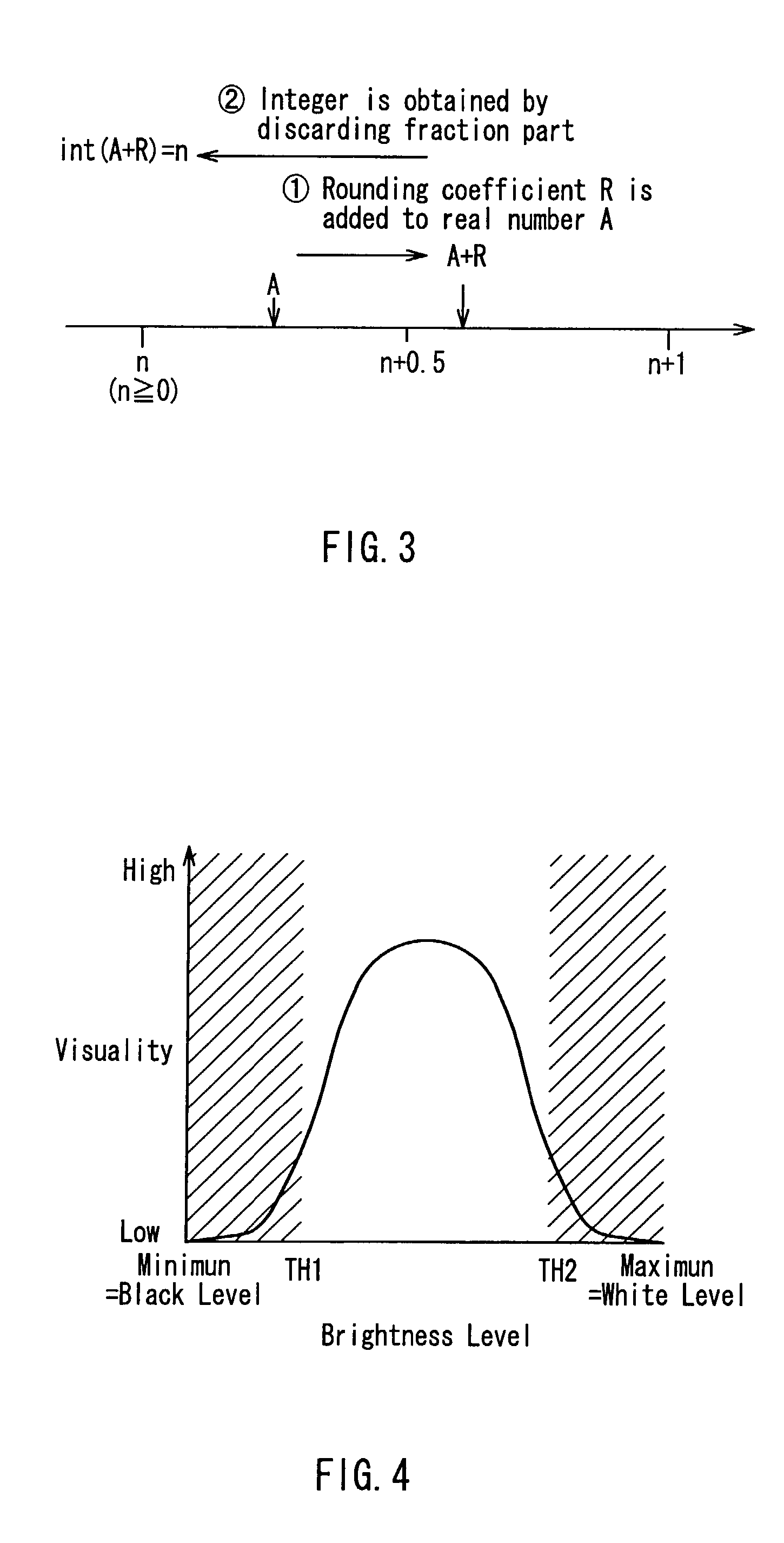
[0030]FIG. 4 illustrates a human visual characteristic with respect to brightness levels. The human vision has a characteristic as shown in FIG. 4, and hence, it is unable particularly to distinguish black portions with brightness levels lower than a certain threshold value TH1 (indicated by hatching in FIG. 4) from one another, and to distinguish white portions with brightness levels higher than a certain threshold value TH2 (TH12) (indicated by hatching in FIG. 4) from one another, even if there are leve...

third embodiment

[0031]The following will describe, as the present embodiment, a method for detecting features of a block by taking advantage of a human visual characteristic with respect to color difference levels. Since an image coding device according to the present embodiment has a configuration identical to that according to the first embodiment, the following description of the present embodiment will focus on the operations of the feature detection means 12 for detecting features of a block and the classification means 13.

[0032]FIG. 5 illustrates a human visual characteristic with respect to color difference levels. The human vision has a characteristic as shown in FIG. 5, and hence, it particularly is able to notice distortion more easily in a portion with a color difference level higher than a threshold value TH3 and with a high color saturation degree (indicated by hatching in FIG. 5). Therefore, in the case where an average of color difference levels of a block is in the foregoing range, ...


PUM


Abstract

To compress and encode an image by dividing the image into units of blocks, a method in which features of each block are detected and different operations are applied according to the features has been used often so as to reduce coding distortion and improve subjective image quality, but this method requires additional information representing features of blocks to be recorded and transmitted together, thereby deteriorating the coding efficiency. A rounding operation with respect to a calculation result is modified so that the rounding operation is varied according to features detected as to each block. By so doing, adaptive compressing and coding is implemented by only the processing upon coding, without recording or transmitting additional information.

Description

BACKGROUND OF THE INVENTION[0001]1. Field of the Invention[0002]The present invention relates generally to an image coding method and device that are used for compressing and encoding image data when the data are recorded or transmitted.[0003]2. Related Background Art[0004]Though there are minor differences in image compressing methods according to whether targets are motion pictures or still pictures, many image compressing methods, for instance, the MPEG2 (motion picture expert group second version) method employed in the digital television broadcasting and the like, and the JPEG (joint photographic experts group) commonly employed in digital still cameras, basically deal with images in a state of being divided into blocks. To obtain the highest-possible-quality decoded images with the smallest possible number of codes, various proposals have been made conventionally. To obtain the high image quality in these image compressing methods is, in other words, to discover an optimal sol...

Claims


Application Information

Patent Timeline
Patent Type & Authority Patents(United States)
IPC IPC(8): G06K9/36G06K9/46H04N19/60G06T9/00H03M7/40H04N1/41H04N19/124H04N19/126H04N19/136H04N19/14H04N19/149H04N19/176H04N19/186H04N19/189H04N19/196H04N19/625H04N19/85
CPCG06T9/007
Inventor SAITO, HIROSHI
Owner GK BRIDGE 1
Why Eureka
Try Eureka