Arithmetic circuit
- Summary
- Abstract
- Description
- Claims
- Application Information
AI Technical Summary
Benefits of technology
Problems solved by technology
Method used
Image
Examples
first embodiment
(First Embodiment)
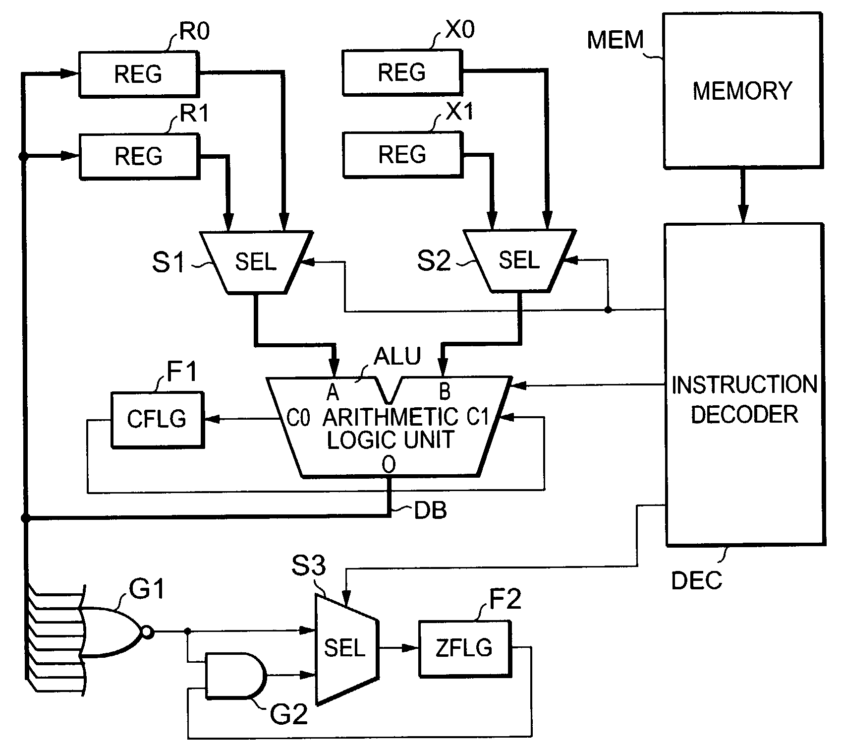
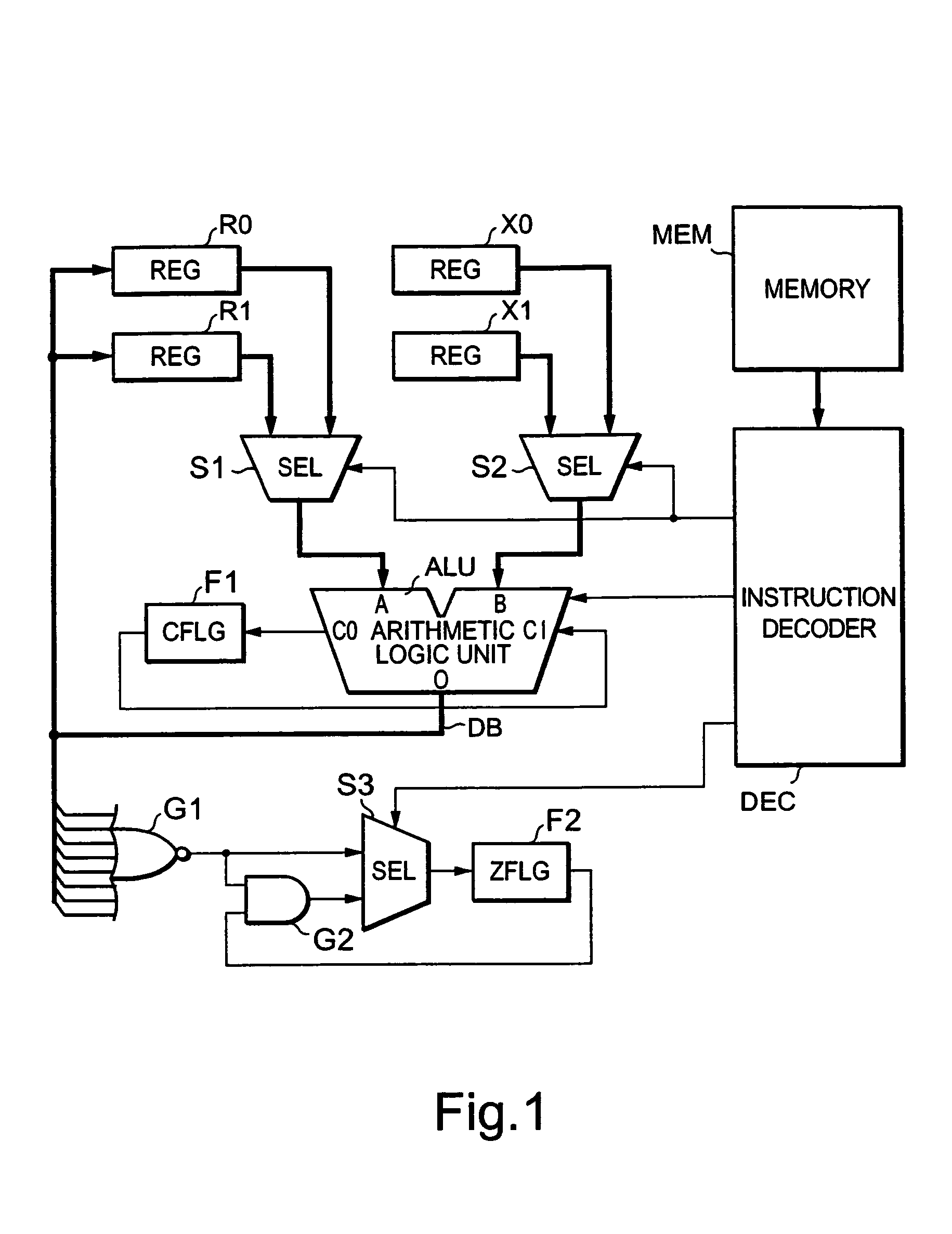
[0021]FIG. 1 is a block diagram of an arithmetic circuit showing a first embodiment of the present invention.
[0022]The arithmetic circuit is one wherein in a microprocessor or the like, an 8-bit adder-subtractor is used to perform addition and subtraction of 16-bit integers. The arithmetic circuit has registers (REG) R0 and R1 each of which sets an augend (or minuend) and stores the result of addition (or subtraction) after its arithmetical operation, and registers X0 and X1 for respectively setting an addend (or subtrahend). Any of the registers R0, R1, X0 and X1 has an 8-bit data width. Lower 8 bits are set to the registers R0 and X0, and upper 8 bit are set to the registers R1 and X1, respectively.
[0023]The values of the 8 bits set to the registers R0 and R1 are supplied to a 8-bit input terminal A of a computing circuit or arithmetic logic unit (e.g., adder-subtractor) ALU through a selector S1, and the values of the 8 bits set to the registers X0 and fX1 are s...
second embodiment
(Second Embodiment)
[0043]FIG. 3 is a block diagram of an arithmetic circuit showing a second embodiment of the present invention. Elements of structure common to the elements shown in FIG. 1 are respectively identified by common reference numerals.
[0044]The arithmetic circuit is one wherein the arithmetic circuit shown in FIG. 1 is provided with a computing circuit (e.g., shifter) SFT, selectors S4, S5 and S6, and a logic circuit (e.g., a two-input logical sum (hereinafter called “OR”) gate) G3. The shifter SFT left-shifts data of 8 bits selected by a selector S1 in one-bit units. Namely, when an unillustrated control signal is supplied from an instruction decoder DEC to the shifter SFT, the shifter SFT shifts 8-bit data supplied to its input terminal I to the left one bit by one bit. At this time, the most significant bit is outputted from a carry output terminal CO of the shifter SFT as a carry signal. Further, “0” is set as the least significant bit, and the 8-bit data correspond...
PUM
 Abstract
Description
Claims
Application Information
 - R&D
- Intellectual Property
- Life Sciences
- Materials
- Tech Scout
- Unparalleled Data Quality
- Higher Quality Content
- 60% Fewer Hallucinations
Browse by: Latest US Patents, China's latest patents, Technical Efficacy Thesaurus, Application Domain, Technology Topic, Popular Technical Reports.
© 2025 PatSnap. All rights reserved.Legal|Privacy policy|Modern Slavery Act Transparency Statement|Sitemap|About US| Contact US: help@patsnap.com


