Synchronous signal producing circuit for controlling a data ready signal indicative of end of access to a shared memory and thereby controlling synchronization between processor and coprocessor

a synchronous signal and signal technology, applied in the direction of program control, multi-programming arrangement, instruments, etc., can solve the problems of reducing the operation speed of the processor and the operation speed of the operation speed, and achieve the effect of reducing the overhead of operations

Inactive Publication Date: 2005-08-09
RENESAS TECH CORP
View PDF8 Cites 68 Cited by
  • Summary
  • Abstract
  • Description
  • Claims
  • Application Information

AI Technical Summary

Benefits of technology

[0008]An object of the invention is to provide a synchronous signal producing circuit and a method of producing a synchronous signal, in which overhead is reduced in operations for synchronizing a processor and a coprocessor.
[0009]Another object of the invention is to provide a synchronous signal producing circuit and a method of producing a synchronous signal, in which a power consumption of a processor is reduced while keeping synchronization between a processor and a coprocessor.
[0010]Still another object of the invention is to provide a processor system, in which overhead is reduced in a whole system.
[0012]Since the first logic circuit issues the signal setting the processor to the wait state based on the signal indicating that the coprocessor is executing the coprocessor instruction as well as the result of comparison by the comparing circuit, a wasteful operation cycle of the processor is not required, and the overhead can be reduced.
[0014]Since the logic circuit issues the signal setting the processor to the wait state based on the signal indicating that the coprocessor is executing the coprocessor instruction as well as the result of comparison by the comparing circuit, a wasteful operation cycle of the processor is not required, and the overhead can be reduced in the whole processor system.
[0016]Since the signal setting the processor to the wait state is issued based on the signal indicating that the coprocessor is executing the coprocessor instruction as well as the result of detection by the comparing circuit, a wasteful operation cycle of the processor is not required, and the overhead of the whole processor system can be reduced.

Problems solved by technology

If the processor uses data in a region of the shared memory, where the execution result of the coprocessor instruction is to be stored, before completion of the coprocessor instruction, this results in an erroneous operation.
However, the foregoing manner in which the processor polls the status flags in the coprocessor requires a wasteful operation cycle for polling by the processor, and therefore suffers from a problem of reduction in operation speed.
This also reduces the operation speed of the processor.

Method used


Image

  • Synchronous signal producing circuit for controlling a data ready signal indicative of end of access to a shared memory and thereby controlling synchronization between processor and coprocessor
  • Synchronous signal producing circuit for controlling a data ready signal indicative of end of access to a shared memory and thereby controlling synchronization between processor and coprocessor
  • Synchronous signal producing circuit for controlling a data ready signal indicative of end of access to a shared memory and thereby controlling synchronization between processor and coprocessor

Examples


first embodiment

(First Embodiment)

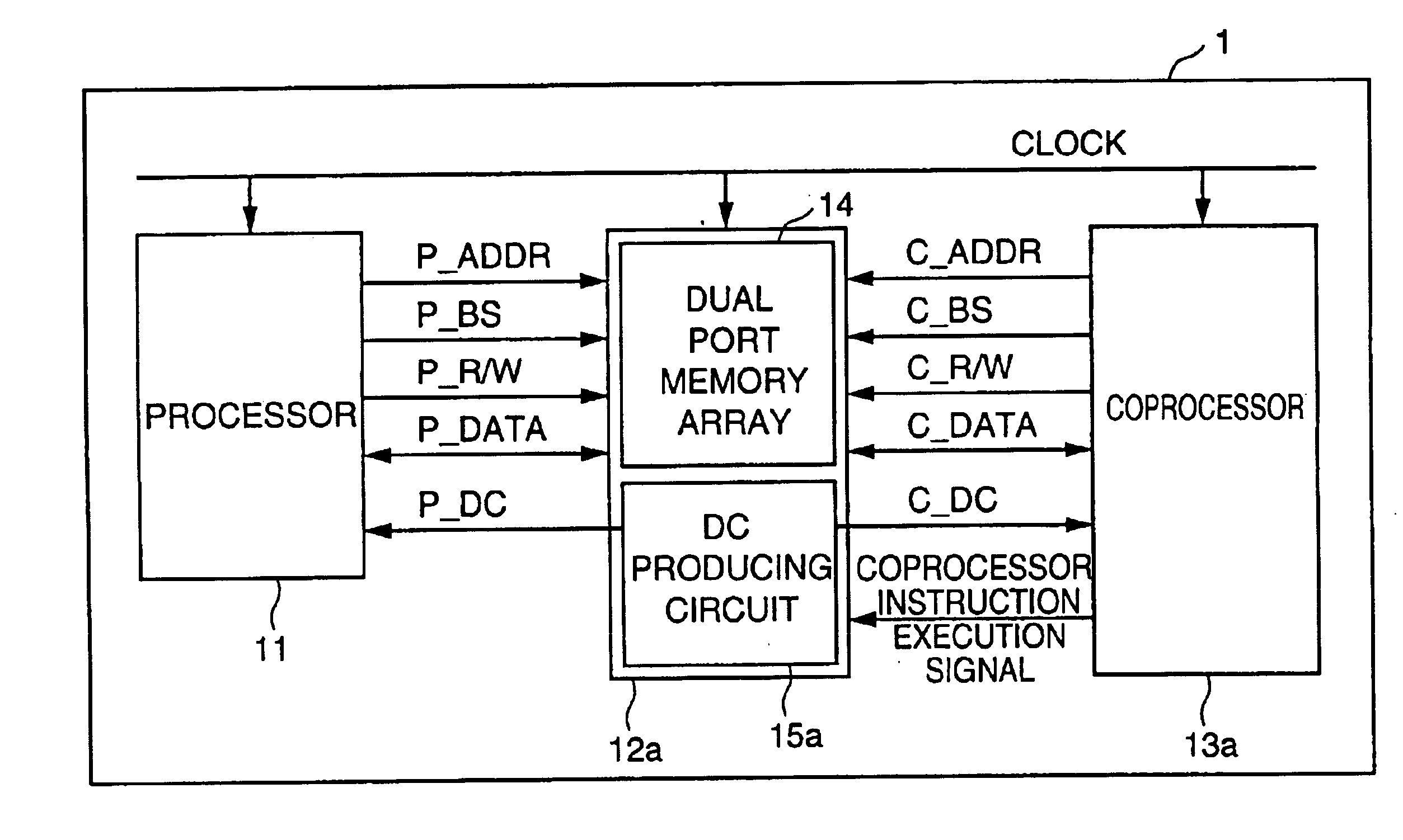
[0036]FIG. 1 is a block diagram showing a schematic structure of a processor system of a first embodiment of the invention. This processor system 1 includes a processor 11, a shared memory 12a and a coprocessor 13a. Processor 11, shared memory 12a and coprocessor 13a are supplied with the same clock. While coprocessor 13a is executing a coprocessor instruction, processor 11 is executing another operation in parallel with coprocessor 13a.

[0037]For accessing shared memory 12a by processor 11, processor 11 issues an address (P_ADDR) signal, a bus start (P_BS) signal, and a read / write (P_R / W) signal. For reading out data by processor 11 from shared memory 12a, processor 11 is supplied with a value of a data bus (P_DATA). For writing data by processor 11 into shared memory 12a, data is output onto data bus (P_DATA). A data ready (P_DC) signal indicates the fact that the data is fixed at the time of access by processor 11 to shared memory 12a.

[0038]For accessing shared...


PUM


Abstract

A synchronous signal producing circuit includes an access inhibit region register for designating an access inhibit region for a processor in a shared memory, a comparing circuit for detecting the access by the processor to the access inhibit region designated in the access inhibit region register, and a logic circuit for issuing a P_DC signal setting the processor to a wait state based on a coprocessor instruction execution signal and a result of the comparison by the comparing circuit.

Description

BACKGROUND OF THE INVENTION[0001]1. Field of the Invention[0002]The present invention relates to a technology for ensuring synchronization between a processor and a coprocessor, and particularly relates to a synchronous signal producing circuit, which controls a data ready signal indicating an end of access to a shared memory, and thereby controls synchronization between the processor and the coprocessor, as well as a processor system and a synchronizing method using such a circuit.[0003]2. Description of the Background Art[0004]In recent years, fast processors have been employed in information processing equipment such as a personal computer as well as home electrical equipment, and it has been increasingly demanded to improve processing speeds. As a measure for improving the processing speeds, a coprocessor may be employed in addition to a processor so that the coprocessor may perform complicated arithmetic operations which cannot be efficiently done by the processor. A shared mem...

Claims


Application Information

Patent Timeline
Patent Type & Authority Patents(United States)
IPC IPC(8): G06F9/38G06F9/30G06F9/52G06F12/00G06F15/16G06F15/177
CPCG06F9/3881
Inventor YAMADA, AKIRA
Owner RENESAS TECH CORP
Why Eureka
Try Eureka