
Electrically operated tuning fork

Inactive Publication Date: 2006-03-14
OPTISCAN
View PDF11 Cites 17 Cited by
  • Summary
  • Abstract
  • Description
  • Claims
  • Application Information

AI Technical Summary

Benefits of technology

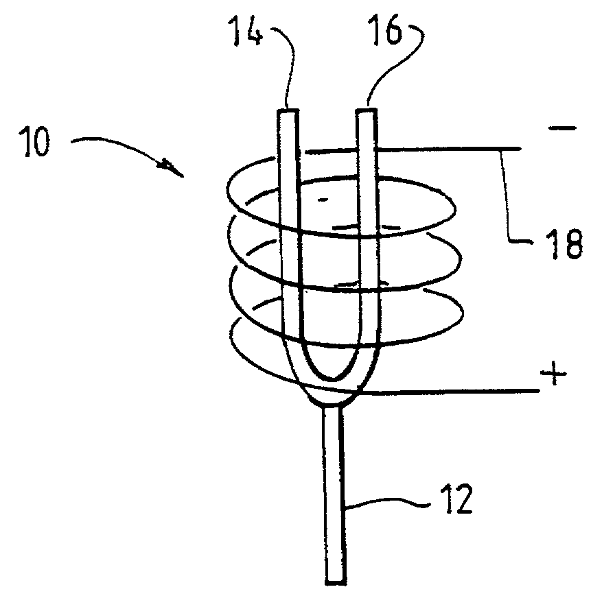
[0010]Thus, this method of vibrating the tine or tines may be less efficient than the existing arrangements (in which the magnetic fields produced by current in the electromagnets are longitudinal); here they are essentially transverse, resulting in mutual repulsion between the tines even in the absence of any other magnetically active material. Preferably the tines are vibrated at the resonant frequency of the tuning fork. With this configuration, both winding strength and packing density of the coil can be maximized by eliminating the need for windings between the tines. The winding is external to the fork and preferably extends over nearly the entire length of the fork, contributing to driving force through induced magnetism even in the base region where the tines are joined. This arrangement therefore allows the largest winding volume, though the winding strength is reduced owing to the larger diameter of the turns compared with the localised windings of the existing designs. However this is compensated by the large cross section available for the winding. At any point along the entire length of the fork the (typically coaxial) winding of the coil contributes to the driving force, even the region beyond the base of the tuning fork.
[0013]The coil may be coaxial with said fork, but need not be strictly so. Indeed, the coil need not be cylindrical. It could, for example, be elliptical, with a major axis of the ellipse oriented in the plane of vibration of the tines, so that a reduction in the total size of the apparatus can be achieved.

Problems solved by technology

Thus, this method of vibrating the tine or tines may be less efficient than the existing arrangements (in which the magnetic fields produced by current in the electromagnets are longitudinal); here they are essentially transverse, resulting in mutual repulsion between the tines even in the absence of any other magnetically active material.

Method used


Image

  • Electrically operated tuning fork
  • Electrically operated tuning fork
  • Electrically operated tuning fork

Examples


Embodiment Construction

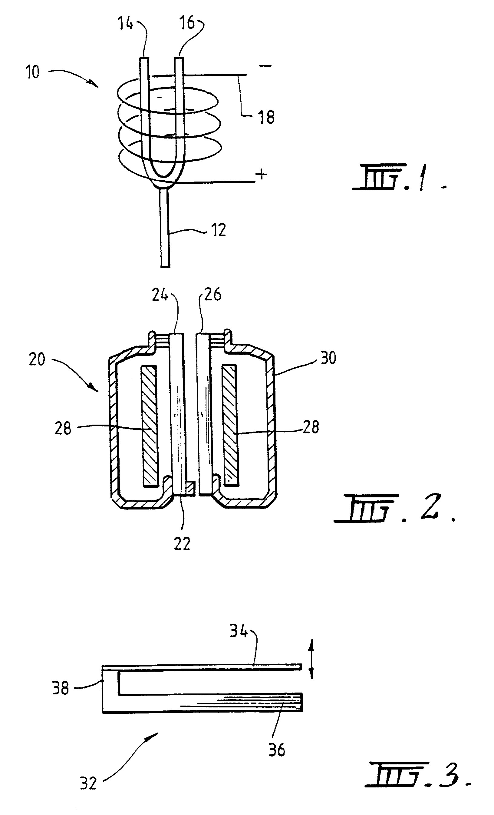
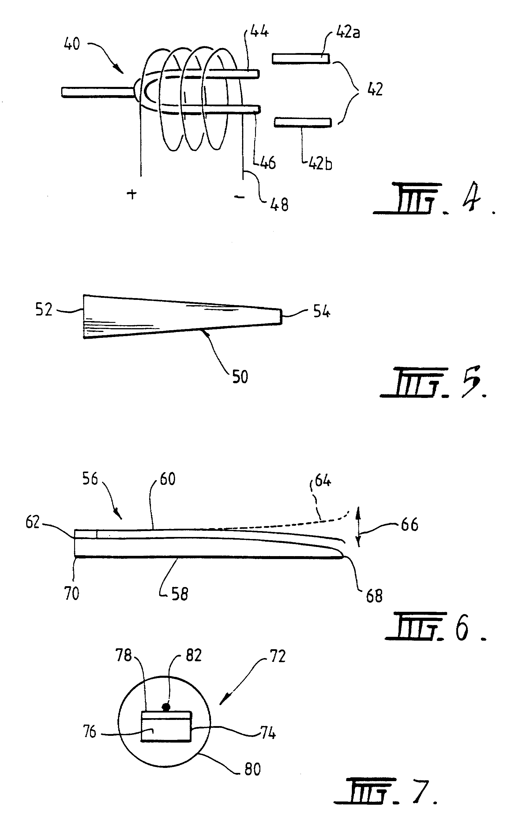
[0048]An electrically operated tuning fork according to a preferred embodiment of the present invention is shown schematically at 10 in FIG. 1. The electrically operated tuning fork 10 includes a tuning fork 12 with tines 14 and 16, and an electrical coil 18 disposed coaxially about tuning fork 12. The tines 14 and 16 project from coil 18 by approximately 15% of their length. Thus, when an electrical current is applied to coil 18, the magnetic field produced by current in the coil is longitudinal and induces magnetic fields in and about tines 14 and 16 that are mutually repulsive, even in the absence of any other magnetically active material. The winding of the coil 18 along almost the full length of the tines 14 and 16 means that the electrically operated tuning fork 10, although of low efficiency, can nevertheless be used to produce sufficiently large magnetic fields to provide the deflection necessary for use in optic fibre scanners, such as optical fibre confocal microscopes.

[00...


PUM


Abstract

An electrically operated tuning fork apparatus includes a tuning fork having a base and a pair of tines. The tines have tips remote from the base, and are formed of or include material in which a magnetic field can be induced. The tuning fork apparatus also includes an electrical coil configured to receive at least a portion of both tines of the tuning fork. At least one of the tines can be vibrated relative to the other of the tines by passing a varying current through the coil to induce mutually repulsive magnetic fields in the tines.

Description

FIELD OF THE INVENTION[0001]The present invention relates to electrically operated tuning forks, of particular but by no means exclusive application in oscillating tuning forks for optical fibre scanning in, for example, endoscopes and microscopes.BACKGROUND OF THE INVENTION[0002]Electromagnets have been used to oscillate tuning forks to form oscillators and compact narrow bank audio filters. More recently these oscillators have been used in optical applications, such as with laser beam choppers and optical fibre scanning.[0003]Existing systems, however, have a number of drawbacks. For example, one optical oscillator includes an optical fibre attached to the tuning fork, to provide a simple and efficient integrated optical scanner. In these existing systems, a pair of electromagnets is used to vibrate the tines of the tuning fork, with the optical fibre attached to one of the tines. Typically the electromagnets are located either between the tines or disposed on opposite sides of th...

Claims


Application Information

Patent Timeline
IPC IPC(8): G01P9/04G01J1/42G02B23/26G02B6/35G02B21/06G02B26/10H03B5/30
CPCG02B26/10
Inventor HARRIS, MARTIN RUSSELLROSMAN, GAVAN EDMUNDRUDGE, JAMES
Owner OPTISCAN
Learn More