Acoustic pick-up

Inactive Publication Date: 2006-08-17
SIEMENS AG
View PDF4 Cites 0 Cited by
  • Summary
  • Abstract
  • Description
  • Claims
  • Application Information

AI Technical Summary

Benefits of technology

[0009] The invention has the advantage that the acoustic pick-up takes the power needed to operate an electronic circuit for signal conditioning from its surroundings so that said power does not have to be supplied to it over separate wires in a cable. As the acoustic pick-up generates the auxiliary power from the acoustic signal requiring to be picked up, sufficient power will always be available for operating the circuit at times when an acoustic signal exceeding a specific minimum intensity is present and a corresponding output signal has to be produced. The output signal can be transmitted to the evaluation device asymmetrically or symmetrically over a cable, for example, or alternatively wirelessly using radio or infrared light.
[0010] The auxiliary power is generated from the electric measurement signal of the piezoelectric measuring element. This has the advantage that no further electroacoustic components will be required in addition to the actual measuring element of the acoustic pick-up.
[0011] When acoustic pick-ups are used for machine diagnosing, in particular for diagnosing valve leakage or damage to a bearing, evaluating a specific frequency range has proved in most cases adequate for obtaining a diagnostic result. It is known from, for instance, DE 199 47 129 A1 how when valve leakage is being diagnosed to distinguish between a lower spectral range in which mainly the valve's operating noises are located and an upper spectral range predominantly containing fault-generated noises in certain operating conditions. The threshold frequency between said two spectral ranges can be selected to be between 50 kHz and, for example, 200 kHz since the operating noises occur predominantly in a range below 120 kHz. A spectral range of the measurement signal above a frequency of 50 kHz is therefore evaluated for detecting faults, which range does not, however, have to begin directly at 50 kHz. Only signal components in that frequency range have to be amplified and transmitted on a wire-bound basis or wirelessly to the evaluation device. The signal supplied by the piezoelectric measuring element is especially powerful in the frequency range between 0 and 50 kHz because the signal components have a substantially greater amplitude therein. The signal components in that range can advantageously be used for generating the power required for operating the conditioning circuit. There is thus advantageously provided a frequency separating filter by means of which the electric measurement signal of the piezoelectric element is separated essentially into an evaluation signal in a first frequency range, which signal is conditioned into a form suitable for transmitting to an evaluation device located outside the housing, and into a supply signal in a second frequency range, which signal supplies the auxiliary power required for operating the conditioning circuit. A frequency separating filter of said type furthermore offers the advantage that the evaluation signal will be falsified only slightly despite the supply signal being derived from the same electric measurement signal.
[0012] A better quality for the auxiliary power for the circuit for signal conditioning and hence a better quality for the output signal will advantageously be achieved if a device for rectifying and smoothing the supply signal is provided.

Problems solved by technology

As an instance of this, defective valve seats will result in leakage flows that produce broadband ultrasonic emissions.

Method used


Image

  • Acoustic pick-up
  • Acoustic pick-up

Examples


Embodiment Construction

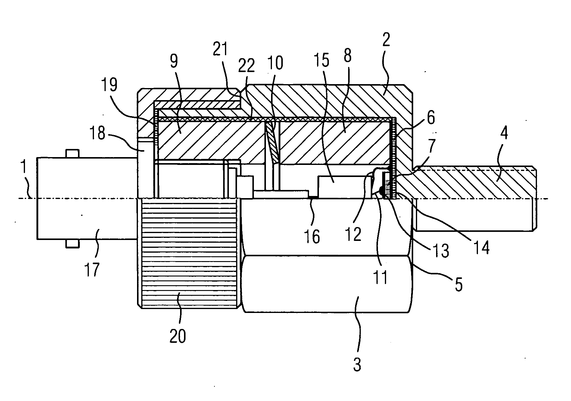
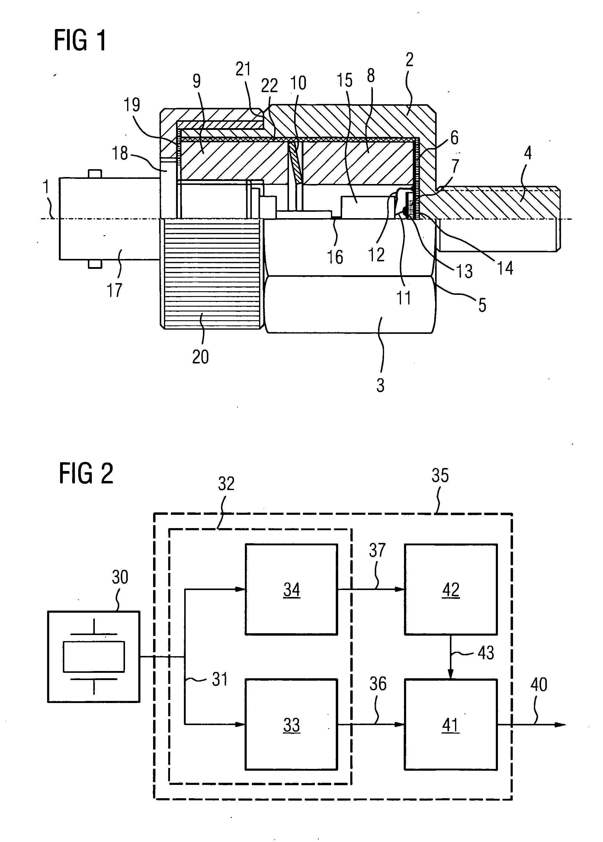
[0016] Shown in the bottom half of FIG. 1, which is to say below an axis 1, is a side view of an essentially rotationally symmetrically structured acoustic pick-up, and in the top half a longitudinal section through said acoustic pick-up.

[0017] According to FIG. 1 the acoustic pick-up has a pot-shaped housing 2 furnished on its exterior with driving flats 3 for a wrench. Provided as a securing means is a threaded stem 4 that can be turned into a corresponding threaded boring at the mounting position. The requisite starting torque can be applied by means of a wrench to ensure good coupling of the vibrations via a contact surface 5 of the housing base at the mounting position. Inside the housing base is an insulating disk 6 of the same material as that also of a piezoelectric element 7 onto which has been soldered a metal-plated side of said insulating disk 6, which side faces a sleeve section 8. Together with a sleeve section 9 and a disk spring 10, said 10, said sleeve section 8 fo...


PUM


Abstract

An acoustic pick-up, particularly an ultrasonic pick-up for acoustically diagnosing machines, for example, for detecting leakage in valves or for diagnosing positions, comprising a piezoelectric measuring element and an electronic circuit that processes the measurement signal into a form that is suited for transmission to an evaluation device. In order that the acoustic pick-up can function without an external auxiliary power supply, means are provided by means of which auxiliary power required for operating the electronic circuit can be generated from the acoustic signal to be picked up.

Description

CROSS REFERENCE TO RELATED APPLICATIONS [0001] This application is the US National Stage of International Application No. PCT / EP2004 / 005826, filed May 28, 2004 and claims the benefit thereof. The International Application claims the benefits of German application No. 10325801.9 DE filed Jun. 6, 2003, both of the applications are incorporated by reference herein in their entirety.FIELD OF INVENTION [0002] The invention relates to an acoustic pick-up, more particularly an ultrasonic pick-up for acoustically diagnosing machines. BACKGROUND OF INVENTION [0003] In many areas of process and power engineering that are of relevance to safety the trouble-free operation of a system depends on the smooth functioning of the machines or machine parts employed. In order to avoid costly, erratic interruptions to operation, any damage to valves or bearings, for instance, should as far as possible be detected at the initial stage, which is to say before a component outage can bring the system to a h...

Claims


Application Information

Patent Timeline
IPC IPC(8): G01H11/08G01N29/14G01M3/24
CPCG01M3/24
Inventor ENS, WOLFGANGPUTTMER, ALF
Owner SIEMENS AG
Why Eureka
Try Eureka