Method for exciting light for optical amplification medium fiber, structure for emitting excited light into optical amplification medium fiber optical fiber amplifier, and optical fiber laser

Active Publication Date: 2006-06-20
THE FUJIKURA CABLE WORKS LTD
View PDF12 Cites 5 Cited by
  • Summary
  • Abstract
  • Description
  • Claims
  • Application Information

AI Technical Summary

Benefits of technology

[0029]Accordingly, an object of the present invention is to provide a method for exciting a light in the optical amplification medium fiber in which the excited light can be emitted so as to be incident into the optical amplification medium fiber highly efficiently, a structure for emitting the excited light so as to be incident into the optical amplification medium fiber, and an optical fiber amplifier and an optical fiber laser which have a superior amplitude.

Problems solved by technology

Therefore, very delicate operations such as adjusting an alignment for an optical axis of a light is necessary.
Also, even though the optical axis is adjusted desirably, there are problems in that an optical axis may be dis-aligned by a mechanical factors such as a vibration and collision or by a temperature condition; thus, a desirable amplification function may be disturbed.
That is, there is a problem in that efficiency for emitting the excited light 224 to be incident into the optical amplification medium fiber 210 is not enough; thus, the light loss is undesirably great.
Therefore, it is very difficult to introduce an excited light into the core efficiently.
Also, if there is a dust on an end surface into which the excited light is emitted to be incident in the rare-earth-doped fiber, there is a concern that the end surface may be damaged by a heat.
Therefore, there is a concern that a section into which the excited light is introduced may be damaged by heat in the double-cladding fiber.
Therefore, there is a problem that the laser light is not output.
Therefore, a problem such as a diminished transmission of the excited light and a dispersion loss may occur in gaps among the optical fibers.
However, such an organic bonding agent has only a low optical power resistance.
If the intensity of the excited light is enhanced for obtaining a higher output of the laser light, the organic bonding agent may be denatured; thus, it is not possible to realize a desirable transparency for the organic bonding agent.
Also, an entire structure which is formed by a plurality of the bundled optical fibers may be damaged by a heat; thus, there may be a case in which the laser light may not be output.

Method used


Image

  • Method for exciting light for optical amplification medium fiber, structure for emitting excited light into optical amplification medium fiber optical fiber amplifier, and optical fiber laser
  • Method for exciting light for optical amplification medium fiber, structure for emitting excited light into optical amplification medium fiber optical fiber amplifier, and optical fiber laser
  • Method for exciting light for optical amplification medium fiber, structure for emitting excited light into optical amplification medium fiber optical fiber amplifier, and optical fiber laser

Examples


first embodiment

[0101]FIG. 7 is a general view for an optical fiber amplifier (hereinafter it is simply called as an “optical fiber amplifier”) according to the present invention.

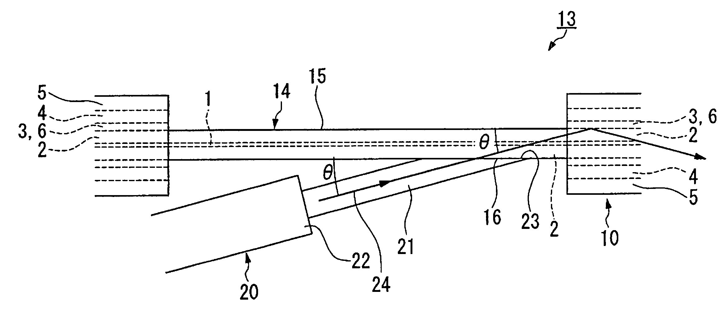
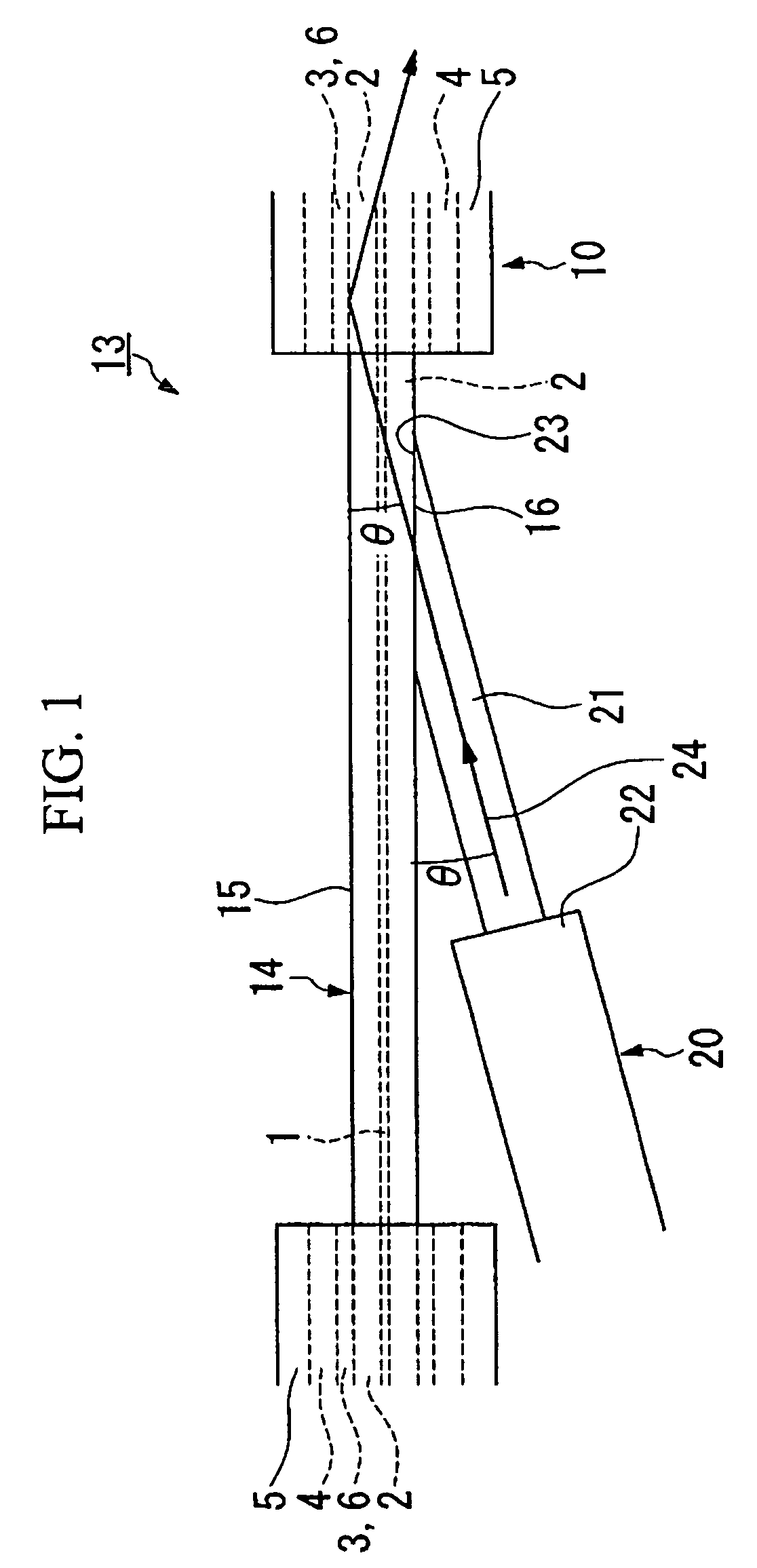
[0102]An optical fiber amplifier 40A has a structure 13 for the incidence of the excited light in which an outer periphery 15 of the inner cladding exposure section 14 which is formed in a part of the optical amplification medium fiber 10 in a longitudinal direction and an end surface 23 of the naked optical fiber 21 in the optical fiber 20 for the excited light incidence are cemented.

[0103]An excited light source 26 is connected to an end surface 25 which is disposed opposite to the end surface 23 of the optical fiber 20 for excited light incidence.

[0104]Furthermore, an end surface 42 of an optical fiber 41 for signal light incidence is melt-bonded to an inputting end 11 of the optical amplification medium fiber 10 so as to form a melt-bonding connecting section 44.

[0105]It is possible to connect the optical amplification...

second embodiment

[0141]FIG. 18 is a general view for showing the optical fiber laser of the present invention.

[0142]In FIG. 18, reference numeral 211 indicates a rare-earth ion-doped fiber. Reference numeral 212, 213 indicate resonating mirrors. Reference numeral 214 indicates an excited LD module. Reference numeral 215 indicates a guide fiber.

[0143]Resonating mirrors 12, 13 are disposed on both end surfaces of the rare-earth-ion-doped fiber 211 in the optical fiber laser according to the present embodiment. Also, four guide fibers 215 extend from the excited LD module 214 such that these guide fibers 215 are connected to different sections on a side of the rare-earth-ion-doped fiber respectively with predetermined intervals. Hereinafter, a connecting section for the rare-earth-ion-doped fiber 211 and the guide fibers 215 is called as an excited light introducing section 217. The excited light is introduced from the guide fiber 215 to the rare-earth-ion-doped fiber 211 in the excited light introduci...

third embodiment

[0165]FIG. 20 is a general view for showing the optical fiber laser of the present invention.

[0166]In FIG. 20, reference numeral 221 indicates a rare-earth ion-doped fiber. Reference numeral 222, 223 indicate a resonating mirrors. Reference numeral 224 indicates an excited LD module. Reference numeral 225 indicates a guide fiber.

[0167]Resonating mirrors 222, and 223 are disposed on both end surfaces of the rare-earth-ion-doped fiber 221 in the optical fiber laser according to the present embodiment. Also, four guide fibers 225 extend from the excited LD module 224 such that these guide fibers 225 are connected to different sections on a side of the rare-earth-ion-doped fiber respectively with predetermined intervals. Hereinafter, a connecting section for the rare-earth-ion-doped fiber 221 and the guide fibers 225 is called as an excited light introducing section 227. The excited light is introduced from the guide fiber 225 to the rare-earth-ion-doped fiber 221 in the excited light i...


PUM


Abstract

An inner cladding exposure section 14 is formed by removing a part of an outer cladding 4 of an optical amplification medium fiber 10 which has a porous layer 3 between the inner cladding 2 and the outer cladding 4 in a longitudinal direction. An end surface 23 of an optical fiber 20 for the excited light incidence is cemented on an outer periphery of the exposed inner cladding 2. The excited light 24 is incident into the optical amplification medium fiber 10 from the optical fiber 20 for the excited light incidence. By doing this, it is possible to provide a method for exciting a light in an optical amplification medium fiber which can realize a superior amplitude while emitting the excited light so as to be incident into the optical amplification medium fiber highly efficiently.

Description

[0001]The present application claims priority from patent application No. 2003-151260 filed May 28, 2003 in Japan, and No. 2003-179850 filed Jun. 24, 2003, the content of which is incorporated herein by reference.BACKGROUND OF THE INVENTION[0002]1. Field of the Invention[0003]The present invention relates to a method of exciting a light for an optical amplification medium fiber which is used in industrial area such as information communication, a laser medical operation, or a laser manufacturing operation; a structure for emitting an excited light into an optical amplification medium fiber; an optical fiber amplifier; and an optical fiber laser.[0004]2. Description of Related Art[0005]For a conventional type of the optical amplification medium fiber as shown in FIG. 12, there has been an optical amplification medium fiber which is provided with an inner cladding 102 around a core 101 into which a rare-earth element is doped, an outer cladding 104 which is disposed on an outer periph...

Claims


Application Information

Patent Timeline
IPC IPC(8): G02B6/02H01S3/067H01S3/094
CPCH01S3/094003H01S3/06708
Inventor SHIMA, KENSUKEKITABAYASHI, TOMOHARUSAKAI, TETSUYA
Owner THE FUJIKURA CABLE WORKS LTD
Why Eureka
Try Eureka