Transmitter/receiver for radio communication, RFID system and receiving method for transmitter/receiver for radio communication

a technology of radio communication and transmitter, which is applied in the direction of near-field systems using receivers, read/write/interrogation/identification systems, instruments, etc., can solve the problems of amplitude difference between the modulation components of the superimposed signal of the transmission signal and the disappearance of the receive signal, so as to improve the identification accuracy in a state where the communication null phenomenon does not occur, and reduce the time required for detecting and bypassing the communication null phenomenon.

Active Publication Date: 2012-10-09
TDK CORPARATION
View PDF24 Cites 3 Cited by
  • Summary
  • Abstract
  • Description
  • Claims
  • Application Information

AI Technical Summary

Benefits of technology

[0018]It is preferable that the first or the third transmitter / receiver for radio communication further comprises a matching circuit connected between the transmission circuit and the antenna circuit, wherein a part of the matching circuit or the matching circuit is also used as the phase shift circuit. If the frequency of a transmission / reception signal is high, impedance matching must be performed between the transmission circuit and the antenna circuit so as to decrease signal loss. According to this configuration, a part or all of the matching circuit for impedance matching is also used as the phase shift circuit, so the device can be downsized and price thereof can be decreased.
[0022]In the above mentioned first to third transmitter / receiver for radio communication, it is preferable that the switching circuit is switched so as to select a greater amplitude demodulation signal. According to this, identification accuracy in a state where the communication null phenomena does not occur can be improved.
[0023]It is also preferable that the above mentioned first to third transmitter / receiver for radio communication further comprises a control circuit which causes the switching circuit to perform switching repeatedly, and causes the switching circuit to stop switching when a demodulation signal for the demodulation circuit can be recognized. According to this configuration, the communication null phenomena can be detected and bypassed independently. Since the switching of the switching circuit can be controlled depending on whether the preamble part of a response signal can be recognized, the time required for detecting and bypassing the communication null phenomena can be decreased.

Problems solved by technology

Therefore when the RFID reader / writer superimposes its own transmission signal and a receive signal from the RFID tag, the transmission signal and the receive signal weaken each other, and when a communication null phenomena occurs, the amplitude difference of modulation components in the superimposed signal of the transmission signal and the receive signal disappears.

Method used


Image

  • Transmitter/receiver for radio communication, RFID system and receiving method for transmitter/receiver for radio communication
  • Transmitter/receiver for radio communication, RFID system and receiving method for transmitter/receiver for radio communication
  • Transmitter/receiver for radio communication, RFID system and receiving method for transmitter/receiver for radio communication

Examples


first embodiment

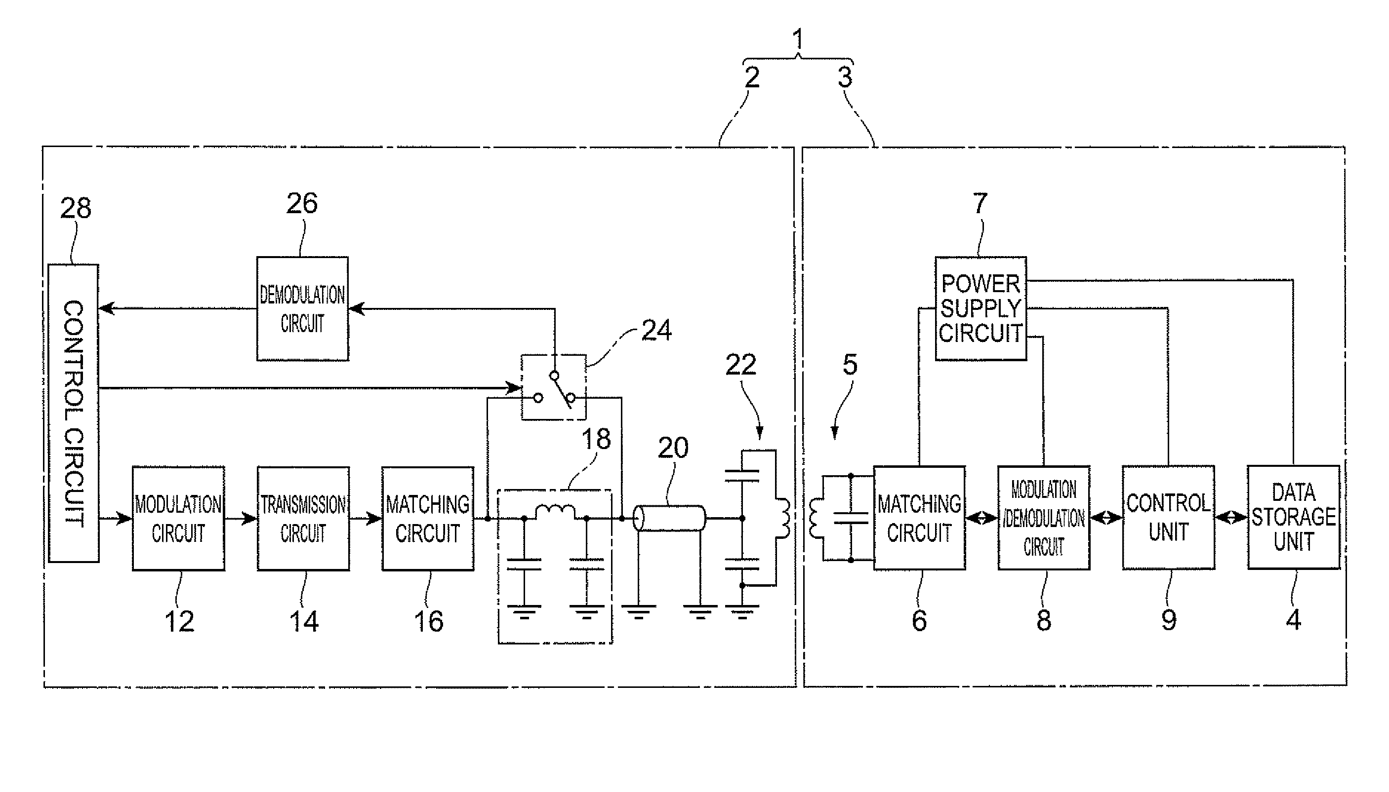
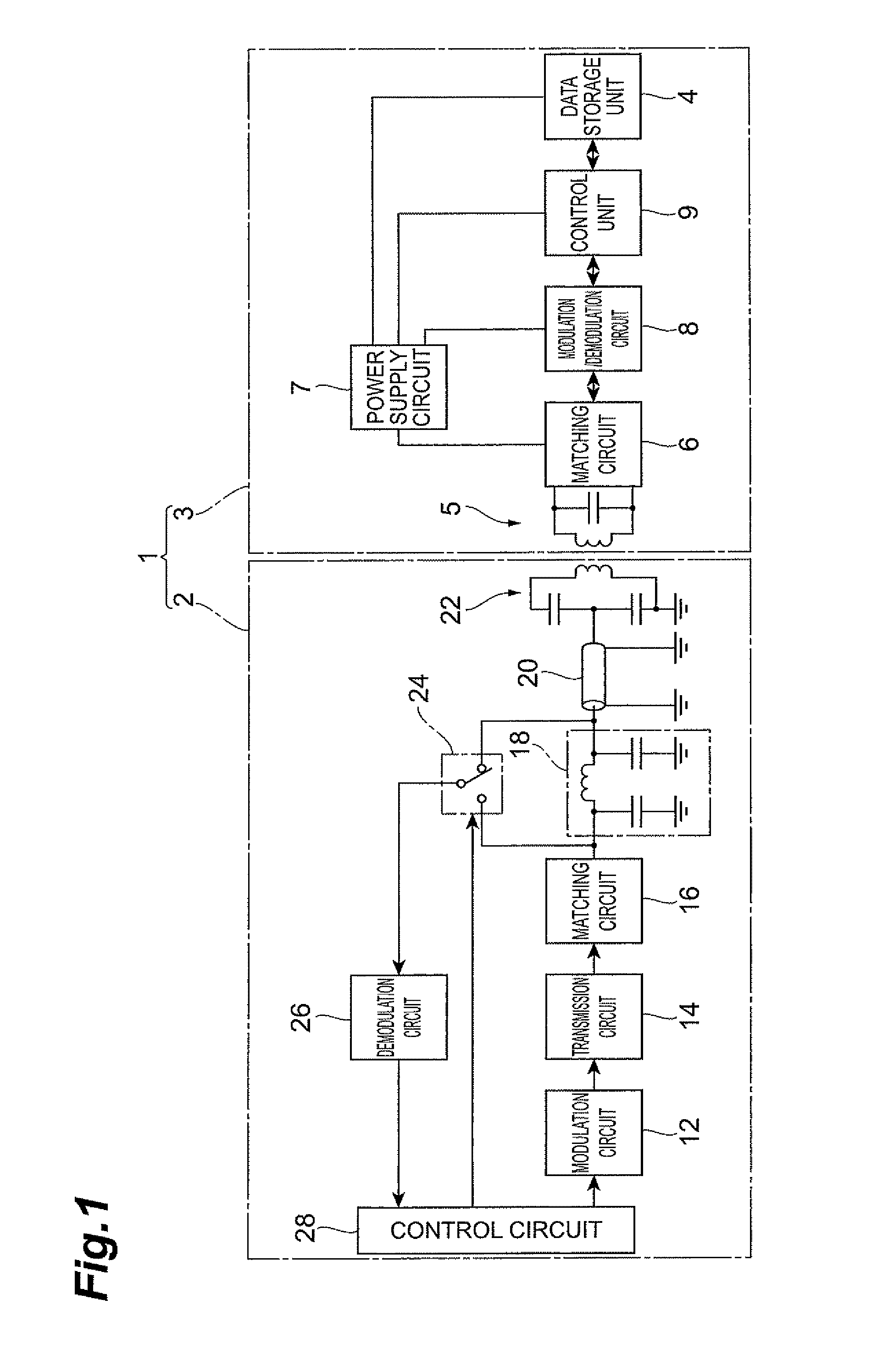
[0041]FIG. 1 is a current diagram depicting an RFID system and an RFID reader / writer according to a first embodiment of the present invention. The RFID system 1 in FIG. 1 comprises an RFID reader / writer 2 and an RFID tag 3. The RFID tag 3 further comprises a data storage unit 4, such as a memory, and this data storage unit 4 can store data, such as ID data, product codes, management codes and management number of visitors. This data is read or written by the RFID reader / writer 2. Specifically, the RFID reader / writer 2 sends a command signal to the RFID tag 3 by radio, and the RFID tag 3 replies with a response signal to this command signal. Receiving this response signal, the RFID reader / writer 2 executes processing corresponding to the response signal (e.g. above mentioned data read, data write).

[0042]The RFID tag 3 comprises an antenna circuit 5, matching circuit 6, power supply circuit 7, modulation / demodulation circuit 8, control unit 9, and data storage unit 4. The antenna circ...

second embodiment

[0085]FIG. 7 is a circuit diagram depicting an RFID system and an RFID reader / writer according to a second embodiment of the present invention. The RFID system 1A shown in FIG. 7 has an RFID reader / writer 2A, instead of the RFID reader / writer 2 in the RFID system 1, which is the difference from the first embodiment. The rest of the configuration of the RFID system 1A is the same as the RFID system 1.

[0086]The RFID reader / writer 2A of the second embodiment of the present invention has a switching circuit 24A, instead of the switching circuit 24 in the RFID reader / writer 2, which is the difference from the first embodiment. The rest of the configuration of the RFID reader / writer 2A is the same as the RFID reader / writer 2.

[0087]The switching circuit 24A switches whether the phase shift circuit 18 is inserted between the matching circuit 16 and the demodulation circuit 26 and the coaxial cable 20 or not, according to a switching signal from the control circuit 28. In other words, the sw...

third embodiment

[0096]FIG. 8 is a circuit diagram depicting an RFID system and an RFID reader / writer according to the third embodiment of the present invention. The RFID system 1B shown in FIG. 8 has an RFID reader / writer 2B, instead of the RFID reader / writer 2 of the RFID system 1, which is the difference from the first embodiment. The rest of the configuration of the RFID system 1B is the same as the RFID system 1.

[0097]The RFID reader / writer 2B according to the third embodiment of the present invention has a matching / phase shift circuit 181B, instead of the matching circuit 16, phase shift circuit 18 and coaxial cable 20, in the RFID reader / writer 2, which is the difference from the first embodiment. The rest of the configuration of the RFID reader / writer 2B is the same as the RFID reader / writer 2.

[0098]The matching / phase shift circuit 18B functions as the above mentioned matching circuit and the phase shift circuit. The matching / phase shift circuit 18B constitutes ladder shaped π type LC filter...


PUM


Abstract

A transmitter / receiver for radio communication according to an embodiment of the present invention has: a transmission circuit for generating a transmission signal; a demodulation circuit for demodulating a receive signal; an antenna circuit for transmitting the transmission signal from the transmission circuit and receiving the receive signal and guiding the receive signal to the demodulation circuit; a phase shift circuit which is connected between the transmission circuit and the antenna circuit; and a switching circuit which switches between outputting a superimposed signal of the transmission signal and the receive signal between the phase shift circuit and the antenna circuit to the demodulation circuit, and outputting a superimposed signal of the transmission signal and the receive signal between the transmission circuit and the phase shift circuit to the demodulation circuit.

Description

BACKGROUND OF THE INVENTION[0001]1. Field of the Invention[0002]The present invention relates to a transmitter / receiver for radio communication using an amplitude demodulation method, an RFID system which uses this transmitter / receiver for radio communication as a RFID reader / writer, and a receiving method for this transmitter / receiver for radio communication.[0003]2. Related Background Art[0004]In an RFID system, information stored in an RFID tag can be read or information can be written to an RFID tag, using an RFID reader / writer (transmitter / receiver for radio communication). For example, an RFID reader / writer sends a command signal to an RFID tag, and the RFID tag replies with a response signal to this command signal. Receiving this response signal, the RFID reader / writer performs a processing corresponding to the response signal (e.g. above mentioned reading information or writing information).[0005]In an RFID tag, a load modulation system is widely used as a response signal re...

Claims


Application Information

Patent Timeline
Patent Type & Authority Patents(United States)
IPC IPC(8): H04B1/38G06K7/00G06K17/00G06K19/07H04B5/02
CPCG06K7/0008H04B5/0062H04Q2213/13095
Inventor KONDO, RYOICHIMOCHIZUKI, SHINICHIROU
Owner TDK CORPARATION
Why Eureka
Try Eureka