Optical rotary adaptor and optical tomographic imaging apparatus using the same

Inactive Publication Date: 2009-10-01
FUJIFILM CORP
View PDF8 Cites 28 Cited by
  • Summary
  • Abstract
  • Description
  • Claims
  • Application Information

AI Technical Summary

Benefits of technology

[0028]As a result, the aiming light beam is multiplexed by using the function which prevents the regularly reflected light beam from being returned while improving the S/N by reducing the unnecessary reflected light in the OCT optical rotary adapter section. Thereby, it is possible to avoid the loss of the OCT signal light beam which loss is caused in the aiming light multiplexing function section incorporated in the conventional optical fiber interferomete

Problems solved by technology

Thus, since the wavelength region of the near-infrared wavelength used in the OCT measuring method is separated from the wavelength region of the visible wavelength of the aiming light beam,

Method used


Image

  • Optical rotary adaptor and optical tomographic imaging apparatus using the same
  • Optical rotary adaptor and optical tomographic imaging apparatus using the same
  • Optical rotary adaptor and optical tomographic imaging apparatus using the same

Examples


first embodiment

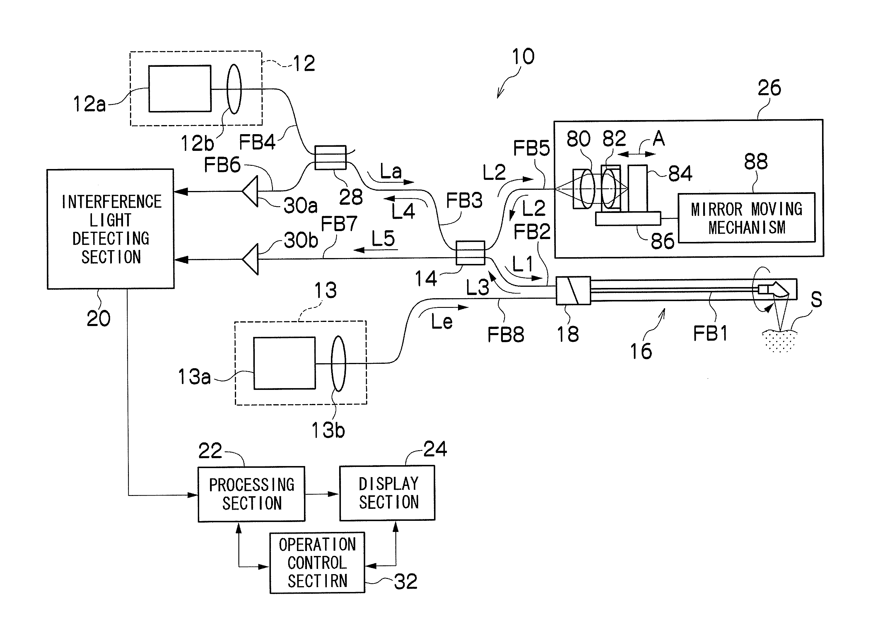
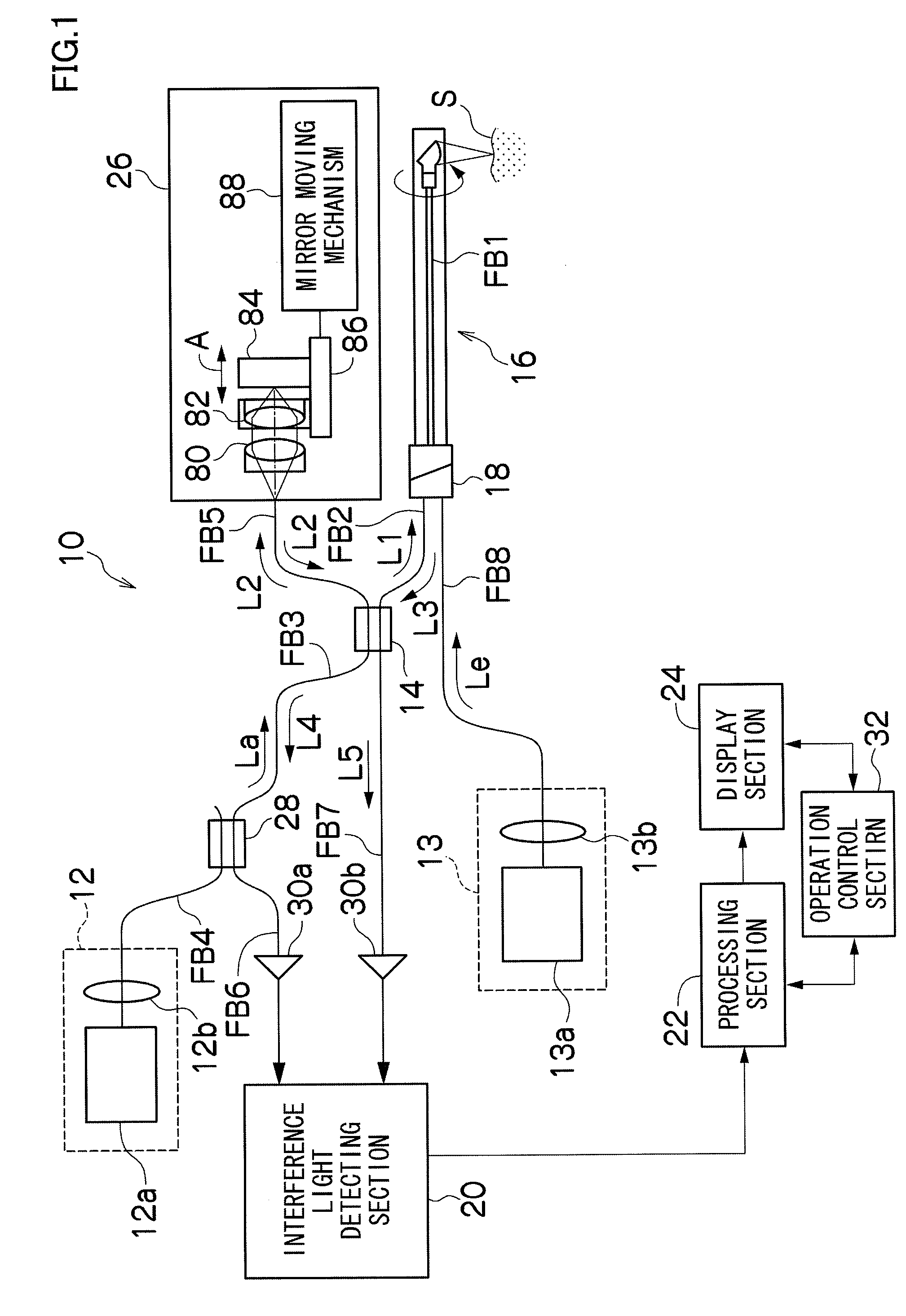
[0039]FIG. 1 is a block diagram showing a schematic configuration of an optical tomographic imaging apparatus using an optical rotary adapter according to the present invention.

[0040]An optical tomographic imaging apparatus 10 according to the present invention shown in FIG. 1, which is used to acquire an optical tomographic image of a measuring object by an optical coherence tomography (OCT) measuring method, includes: a first light source (first light source unit) 12 which emits a light beam for measurement La; an optical fiber coupler (branching / multiplexing section) 14 which branches the light beam La emitted from the first light source 12 into a measuring light beam (first luminous flux) L1 and a reference light beam L2, and which multiplexes the reference light beam L2 with a return light beam L3 from a measuring object S as a subject, to generate an interference light beam L4; an optical probe 16 including a rotation side optical fiber FB1 which guides the measuring light bea...

second embodiment

[0132]Next, there will be described an optical rotary adapter according to the present invention.

[0133]FIG. 4 is a schematic sectional view of an optical rotary adapter according to the second embodiment.

[0134]As shown in FIG. 4, an optical rotary adapter 218 according to the second embodiment is configured such that the positions of the dichroic mirror 101b and the optical-axis compensating plate 101a of the multiplexing device 110 in the optical rotary adapter 18 of the above described first embodiment are replaced in the light traveling direction and their arrangement is reversed.

[0135]That is, in a multiplexing device 210 arranged in the parallel light beam forming section in the fixed sleeve 38 of the present embodiment, the dichroic mirror 101b is arranged on the side nearer to the fixed side collimator lens 42, and the optical-axis compensating plate 101a is arranged on the side nearer to the rotation side collimator lens 50. Further, the dichroic mirror 101b and the optical-...

third embodiment

[0139]Next, there will be described a third embodiment according to the present invention.

[0140]FIG. 5 is a schematic sectional view showing an optical rotary adapter according to the third embodiment.

[0141]As shown in FIG. 5, in an optical rotary adapter 318 of the third embodiment, a multiplexing device 310 is configured by using a trapezoidal prism 201 having two surfaces which face each other and are inclined at respective angles having the same magnitude in the opposite directions, instead of the dichroic mirror 101b and the optical-axis compensating plate 101a of the multiplexing device 110 in the optical rotary adapter 18 according to the above described first embodiment.

[0142]The trapezoidal prism 201 is fixed in the fixed sleeve 38 by a prism holder 202 and a prism fixing ring 203. The two oppositely facing surfaces 201a and 201b positioned in the light traveling direction of the trapezoidal prism 201 are respectively formed at angles having the same magnitude in the opposi...


PUM


Abstract

An optical rotary adapter is featured by including: a fixed side optical fiber which is fixedly supported by a fixed sleeve and which has an end surface inclined with respect to a plane perpendicular to the optical axis of the optical fiber; a fixed side collimator lens which is arranged to be separated from the inclined end surface of the fixed side optical fiber by a predetermined interval; a rotation side optical fiber which is fixedly supported substantially at the center of a rotatably supported rotary cylinder, which is arranged to face the fixed side collimator lens, and which has an end surface inclined with respect to a plane perpendicular to the optical axis of the fixed side collimator lens; a rotation side collimator lens which is fixedly supported by the rotary cylinder, and which is arranged between the fixed side collimator lens and the rotation side optical fiber so as to be separated from the inclined end surface of the rotation side optical fiber by a predetermined interval; a second luminous flux optical fiber which guides a second luminous flux having a function different from that of a first luminous flux as a measuring light beam to the inside of the fixed sleeve; and a multiplexing device which is provided between the fixed side collimator lens and the rotation side collimator lens, and which multiplexes the first luminous flux with the second luminous flux.

Description

BACKGROUND OF THE INVENTION[0001]1. Field of the Invention[0002]The present invention relates to an optical rotary adapter and an optical tomographic imaging apparatus using the optical rotary adapter. More particularly, the present invention relates to an optical rotary adapter configured to rotatably connect between optical fibers which, in order to acquire an optical tomographic image of a measuring object, guide a measuring light beam to the measuring object and guide a return light beam from the measuring object, and relates to an optical tomographic imaging apparatus which irradiates a measuring object with a light beam and which acquires an optical tomographic image of the measuring object from a return light beam reflected from the measuring object.[0003]2. Description of the Related Art[0004]Conventionally, there is known an optical tomographic imaging apparatus using an optical coherence tomography (OCT) measuring method as a method for acquiring a tomogram without cutting...

Claims


Application Information

Patent Timeline
IPC IPC(8): G01B9/02G02B27/30
CPCA61B5/0066A61B5/6852G01J1/0407G01J1/0422G02B6/32G01B9/02061G01B9/02007G01B9/02027G01B9/0205G01B9/02091G02B6/3604
Inventor TOIDA, MASAHIRO
Owner FUJIFILM CORP
Why Eureka
Try Eureka