Camshaft adjuster

a technology of camshaft and adjuster, which is applied in the direction of non-mechanical valves, valve arrangements, machines/engines, etc., can solve the problems of no longer playing a decisive role in the direction of unbalance or unsatisfactory roundness of magnet armatures, and the possibility of torque transmission by slippage is scarce, so as to achieve small air gaps, low manufacturing complexity, and minimal frictional losses

Inactive Publication Date: 2006-03-14
DAIMLER AG
View PDF6 Cites 10 Cited by
  • Summary
  • Abstract
  • Description
  • Claims
  • Application Information

AI Technical Summary

Benefits of technology

[0010]Preferably, the magnet armature is seated fixedly on an armature plunger whose free end face is in loose contact with the control piston or spool or with a part fixedly connected to the latter. The functioning of the electromagnet can be tested independently of the 4 / 2-way valve, for example before assembly. The design according to the invention achieves the situation where no constraining forces occur between the magnet armature and the control piston as a result of manufacture or assembly errors, so that minimum frictional losses occur in all operational ranges, even at extremely variable temperatures. Furthermore, the size of the gap between the control cylinder and the control piston has no effect on the air gap between the magnet armature and the magnet coil, so that small air gaps can be realized with low manufacturing complexity. As a result of these measures, the full performance of the repelling magnet is available for the adjusting movement of the control piston, whereby a rapid response behavior of the control valve and therefore also of the camshaft adjuster is achieved even at low temperatures of approximately −20° C. An unbalance or unsatisfactory roundness of the magnet armature no longer plays a decisive role as a result of the decoupling of the magnet armature from the rotating camshaft, the rotation not being transmitted, or at least not to a significant degree, via the contact faces between the armature plunger and the journal of the control piston.

Problems solved by technology

As a result of these measures, the full performance of the repelling magnet is available for the adjusting movement of the control piston, whereby a rapid response behavior of the control valve and therefore also of the camshaft adjuster is achieved even at low temperatures of approximately −20° C. An unbalance or unsatisfactory roundness of the magnet armature no longer plays a decisive role as a result of the decoupling of the magnet armature from the rotating camshaft, the rotation not being transmitted, or at least not to a significant degree, via the contact faces between the armature plunger and the journal of the control piston.
At the same time, the contact faces are reduced as a result, so that torque transmission by slip is scarcely possible.

Method used


Image

  • Camshaft adjuster
  • Camshaft adjuster

Examples


Embodiment Construction

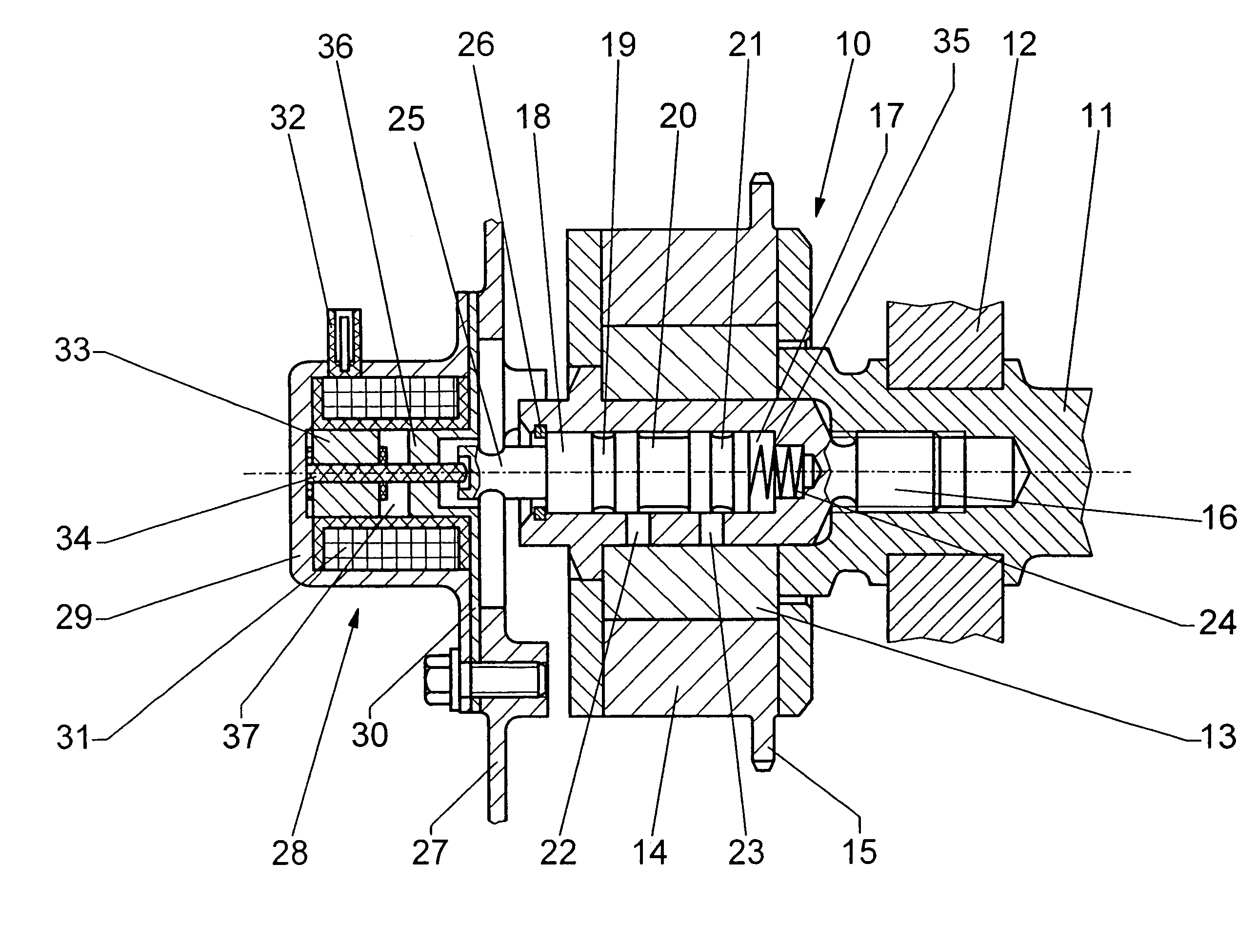
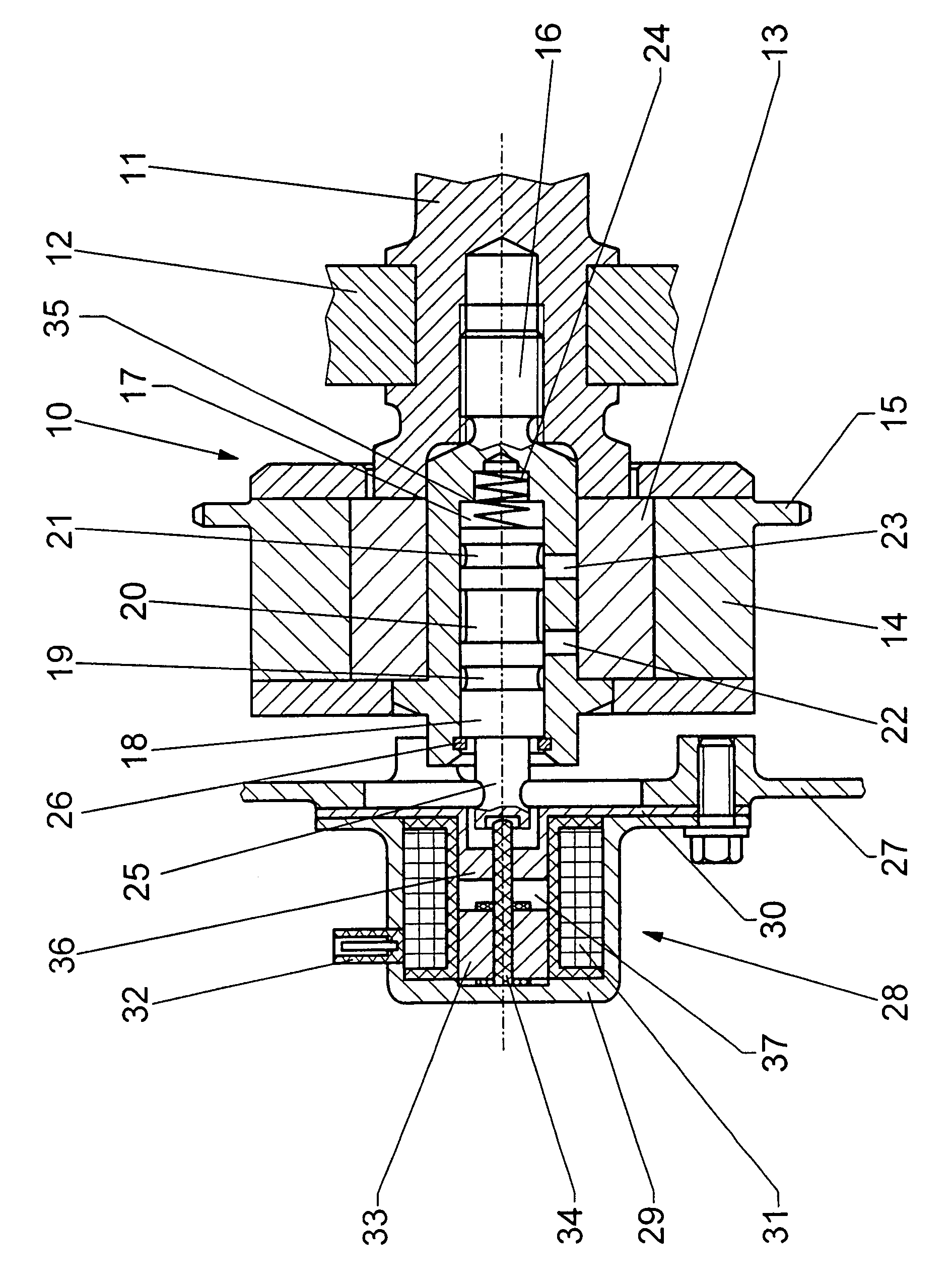
[0015]A camshaft 11 is rotatably mounted in a casing wall 12 of an internal combustion engine (not shown). A camshaft adjuster 10 is fastened to the end of the camshaft 11 by means of a central clamping screw 16 which is screwed into the camshaft 11. The camshaft adjuster 10 has an inner part 13 and an outer part 14, the inner part 13 being connected fixedly to the camshaft 11 so as to rotate with it, while the outer part 14 has a chain sprocket 15 for driving purposes. The inner part 13 can be displaced hydraulically by a rotational angle relative to the outer part 14. A hydraulic displacing mechanism (not shown in detail) can be configured in the manner as described for example in DE 196 54 926 C2 or DE 198 17 319 A1.

[0016]A hydraulic pressure medium is fed to the hydraulic adjusting mechanism via a 4 / 2-way control valve, whose control piston 18 is arranged axially displaceably in a control cylinder 17 which is integrated in the clamping screw 16. The control cylinder 17 has contr...


PUM


Abstract

In a camshaft adjuster having a 4 / 2-way valve which rotates with the camshaft and includes a hydraulic control valve with a hydraulic control spool or piston, which is actuated in a control cylinder against the force of a compression spring between two end stops by a magnet armature of an electromagnet which is fastened to a control casing, the electromagnet is a repelling proportional magnet, whose magnet armature is seated fixedly on an armature plunger whose free end face is in contact with the control spool or with a part fixedly connected to the latter for moving the control spool against the force of the compression spring to actuate the hydraulic control valve so as to control fluid admission to the camshaft adjuster, the working stroke of the electromagnet exceeding that of the control spool.

Description

[0001]This is a Continuation-In-Part application of international application PCT / EP03 / 01527 filed Feb. 15, 2003 and claiming the priority of German application 102 11 467.6 filed Mar. 15, 2002.BACKGROUND OF THE INVENTION[0002]The invention relates to a camshaft adjuster supported for rotation with the camshaft and including a valve spool disposed in a cylinder opening for actuation therein against the force of a compression spring.[0003]DE 196 11 365 discloses such a camshaft adjuster for an internal combustion engine, which adjuster is fastened at one end of a camshaft by means of a central clamping screw. The camshaft adjuster has an outer part which is driven via a chain sprocket and in turn drives an inner part which is connected fixedly to the camshaft for rotation therewith. The rotational angle position of the outer part relative to the inner part can be adjusted hydraulically. An electromagnetically actuated control valve is provided whose control piston is guided axially d...

Claims


Application Information

Patent Timeline
Patent Type & Authority Patents(United States)
IPC IPC(8): F01L1/34F01L1/344F01L9/04
CPCF01L1/34F01L1/344F01L2001/3443F01L2001/34426F01L1/3442
Inventor PLANK, JENSSCHMIDT, PETER
Owner DAIMLER AG
Why Eureka
Try Eureka