Method and apparatus for cleaning a fractured interval between two packers

a technology of perforated casing and method, which is applied in the field of wells, can solve the problems of tool and casing erosion, and the ineffective cleaning of slurry remaining in the annulus interval between the packers, and achieve the effects of reducing the flow rate of the tool passage, and reducing the erosion of the tool componen

Inactive Publication Date: 2006-03-14
SCHLUMBERGER TECH CORP
View PDF22 Cites 43 Cited by
  • Summary
  • Abstract
  • Description
  • Claims
  • Application Information

AI Technical Summary

Benefits of technology

[0008]It is a principal feature of the present invention to provide a straddle packer tool and method of its use for accomplishing downhole treatment of a selected interval in a manner and through the use of a system that minimizes erosive wear of well tool components by the abrasive action of slurry that is utilized during well treatment.
[0009]It is another feature of the present invention to provide a straddle packer tool that is designed with an out and in flow path from the tool to an annular interval between the tool and casing, which promotes efficient and effective cleaning of residual slurry and proppant from the annular interval and the straddle packer tool, thus enabling the tool to be easily moved to a different interval or to enable the tool to be easily extracted from the well.
[0014]The out and in flow path of the straddle tool also greatly reduces erosion of the straddle tool and the casing opposing the outlet port. The out and in configuration of the tool causes the flow path of the abrasive proppant laden formation fracturing slurry to have two gentle bends as the fluid flow is diverted from the tool bore through the outlet port and into the casing-tool annulus. This gentle bend flow diverting characteristic is in contrast to the two abrupt 90 degree bends of the fluid flow path that are employed in typical prior art straddle packer formation fracturing tool designs. A specially shaped diverter plug is located in the outlet mandrel of the tool and functions to channel slurry from the tool bore through the outlet port and into the casing-tool annulus. This diverter plug is fabricated from a sacrificial material that erodes at a prescribed rate in the presence of flowing proppant-laden fracturing fluid. This controlled erosion of the diverter plug, as it assists the port geometry in diverting fluid from the outlet mandrel, through the outlet port, and into the annulus between the well casing and the tool, distributes impingement of the flowing fluid to a larger surface area of the tool and the well casing than is usually the case and minimizes the velocity of the fluid flow and the erosion damage on the outlet mandrel ports and the well casing, resulting in increased tool component life.
[0015]The diverter plug is shaped to direct the flow traveling between the outlet ports into the exit stream. Without this shape, high velocity fluid travels between the ports to the bottom of the outlet port slot and then makes an abrupt turn to exit the outlet port with the other fluid. This sudden change of direction and the increased flow rate caused by more fluid exiting the bottom of the outlet port slot, increases erosion at the bottom edge of the outlet port. This uncontrolled erosion can rapidly cut through the sidewall of the outlet port and can eventually cut into the bypass ports or passages of the tool. This event terminates the well servicing procedure and greatly increases the potential for the tool getting stuck in the well. In addition, the diverter plug is composed of a sacrificial material and is designed to erode at a prescribed rate. The high velocity slurry of the fracturing job erodes the diverter as it is redirected through the outlet ports. The high velocity fluid resists this redirection and as a result more fluid exits the port at the diverter plug interface. More flow means higher velocity, which also means the erosion rate of the out sub is greatest near the diverter plug interface. As the diverter plug erodes, the location of the diverter-out sub interface moves down the port distributing the erosion over a large portion of the port. This controlled erosion increases out sub life. The rate of erosion of the diverter valve can be changed by the use of different materials, various treatments to the material, such as hardness, and by changes in geometry (impingement angle).

Problems solved by technology

When a fracturing treatment is performed on a zone isolated by packers, two problems are prevalent: 1) erosion of the tool and casing due to high velocity flow of abrasive fluids, and 2) cleanup of slurry / proppant in the annular area between the casing and the isolation tool.
According to this arrangement, which employs no reverse circulation, the slurry remaining in the annulus interval between the packers may not be effectively cleaned.

Method used


Image

  • Method and apparatus for cleaning a fractured interval between two packers
  • Method and apparatus for cleaning a fractured interval between two packers
  • Method and apparatus for cleaning a fractured interval between two packers

Examples


Embodiment Construction

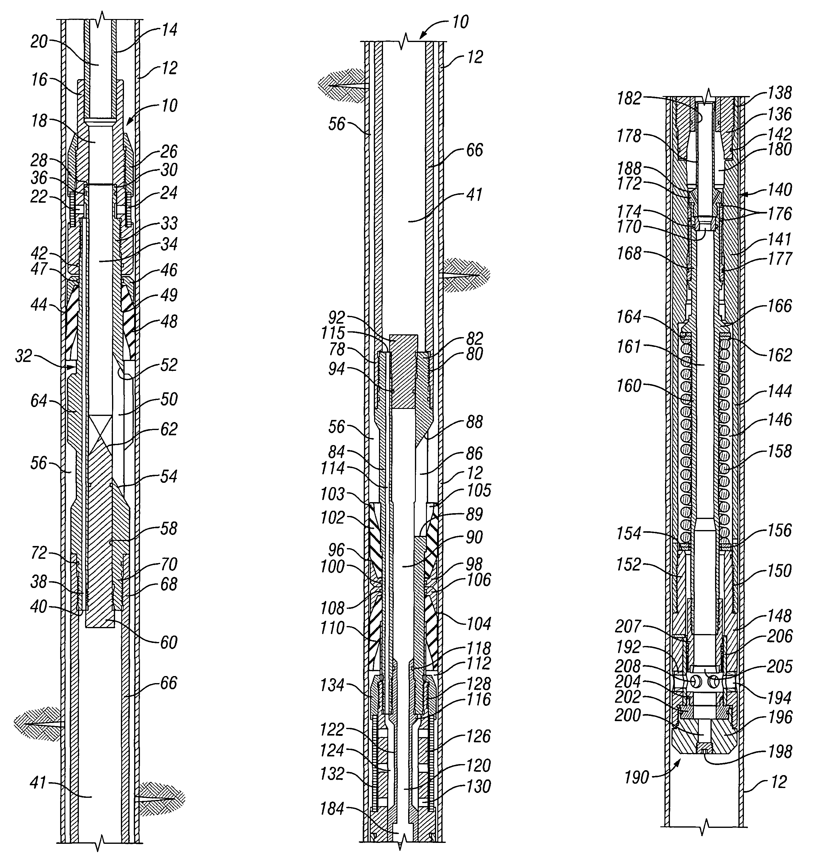
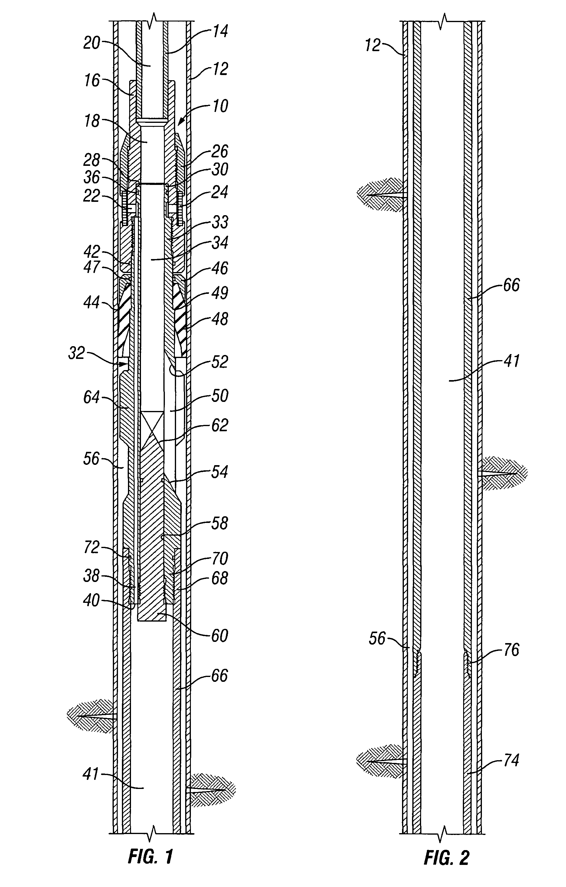
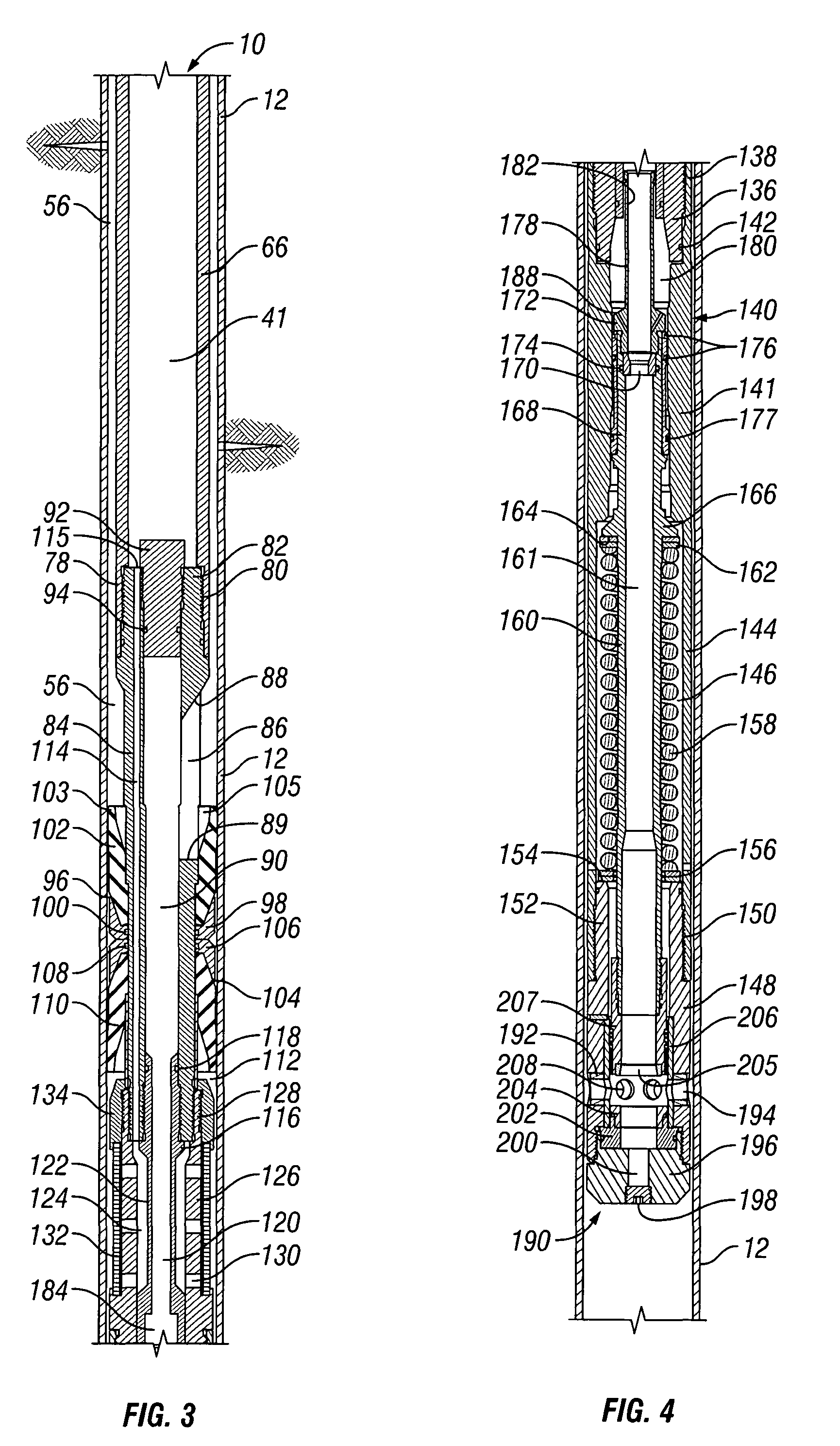
[0026]Referring now to the drawings and first to FIGS. 1–4, a straddle tool embodying the principles of the present invention is shown generally at 10 and is shown located within a well casing 12. A tubing string 14, such as a string of coiled tubing, handled by a tubing conveyance system, is run into the wellbore to convey the straddle tool 10 to the location of the casing perforations that communicate with the subsurface zone to be subjected to fracturing or other treatment. The tubing string 14 is mounted to a tool coupling member 16 which defines a flow passage 18 that is in communication with a flow passage 20 of the tubing string 14. The tool coupling member 16 defines a plurality of by-pass ports 22 that are surrounded by a by-pass screen 24 which is secured within a screen seat by a screen retainer element 26 that is threaded to the tool coupling member 16. The tool coupling member 16 defines an annular internal pocket 28 that receives the upper tubular end 30 of a tubular o...


PUM


Abstract

A method and apparatus for fluid treatment of a selected interval of a well and then cleaning the selected interval and the apparatus of treatment residue. An straddle tool is run into the well to treatment depth on fluid supplying tubing and has upper and lower packers that establish sealing with the casing and define an annular interval between the packers and between the tool and casing. Fluid, such as fracturing fluid, is pumped through the tubing to the tool and is diverted through an outlet port of the tool into an upper portion of the annular interval. Fluid then flows from a lower portion of the annular interval through an inlet port below the outlet port and at low flow rate is dumped into the casing through a pressure responsive dump valve. The outlet port and inlet port are located to accomplish cleaning of residue from the packers.

Description

CROSS-REFERENCE TO RELATED APPLICATIONS[0001]This application claims priority from Provisional Application 60 / 422,543, filed Oct. 31, 2002, which is incorporated herein by reference.BACKGROUND OF THE INVENTION[0002]1. Field of the Invention[0003]This invention pertains generally to wells for production of petroleum products from subsurface earth formations and more particularly concerns completion systems for wells, including formation fracturing and other treatment for enhancement of well production. Even more specifically, the present invention concerns a method and apparatus for cleaning a fractured or otherwise treated perforated casing interval between spaced packers to permit repositioning or removal of the apparatus.[0004]2. Description of Related Art[0005]When a fracturing treatment is performed on a zone isolated by packers, two problems are prevalent: 1) erosion of the tool and casing due to high velocity flow of abrasive fluids, and 2) cleanup of slurry / proppant in the an...

Claims


Application Information

Patent Timeline
Patent Type & Authority Patents(United States)
IPC IPC(8): E21B33/124E21B37/00E21B37/08E21B43/26
CPCE21B43/26E21B37/08
Inventor COSTLEY, JAMES M.ESLINGER, DAVID M.SHEFFIELD, RANDOLPH J.MCKEE, L. MICHAEL
Owner SCHLUMBERGER TECH CORP
Why Eureka
Try Eureka