Front panel of a motor vehicle comprising a bumper beam

a technology for front panels and motor vehicles, which is applied in the direction of monocoque constructions, superstructure subunits, stationary conduit assemblies, etc., can solve the problems of large overall dimensions and inability to be easily placed elsewher

Inactive Publication Date: 2006-03-14
VALEO THERMIQUE MOTEUR
View PDF5 Cites 8 Cited by
  • Summary
  • Abstract
  • Description
  • Claims
  • Application Information

AI Technical Summary

Benefits of technology

[0008]It will be observed that the location of the heat exchanger below the bumper beam allows optimization of the overall dimensions.

Problems solved by technology

This technique has a major disadvantage of overall dimensions.
Furthermore, they cannot easily be placed elsewhere.

Method used


Image

  • Front panel of a motor vehicle comprising a bumper beam
  • Front panel of a motor vehicle comprising a bumper beam
  • Front panel of a motor vehicle comprising a bumper beam

Examples


Embodiment Construction

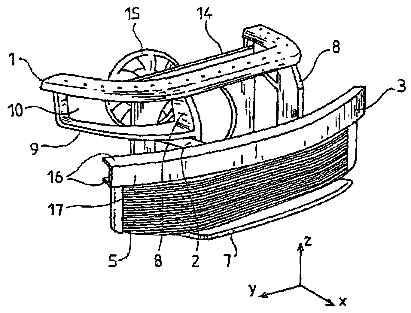
[0027]Reference will firstly be made to FIG. 1. The front panel of a motor vehicle shown in this figure comprises an upper cross-piece 1 whose ends are bent and designed to be fixed onto upper side members (not shown) of the vehicle. Two vertical upright members 8 proceed from the cross-piece 1. Braces 9 are connected to the cross-piece 1 and to the upright members 8 in order to delimit the housings 10 intended to receive the vehicle's headlamps. The vertical upright members 8 are intended to be fixed to lower side members 2 of the vehicle.

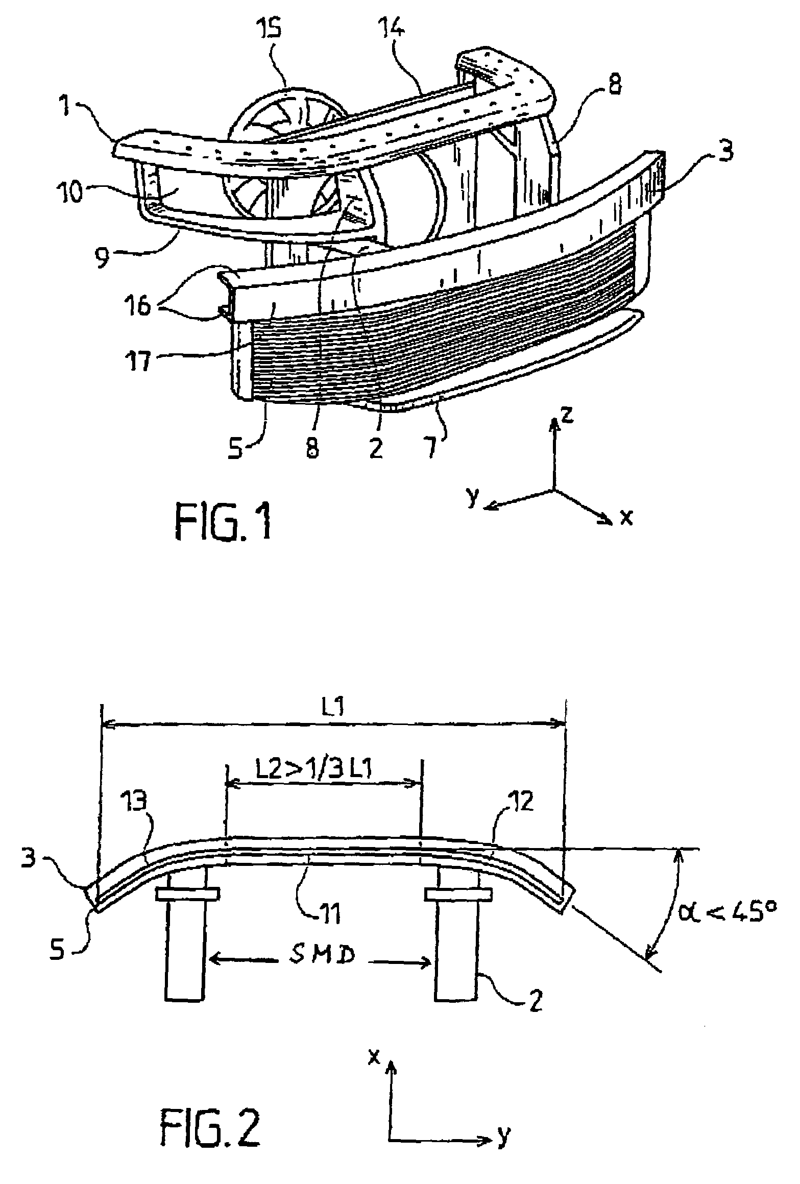
[0028]Furthermore, the front panel comprises a bumper beam 3 fixed to the lower side members 2. In one possible embodiment, the bumper beam 3 is fixed to the side members 2 by screwing.

[0029]The front panel also comprises a lower beam 7, called the pedestrian beam, intended to protect a pedestrian in the event of a frontal collision with the latter. This beam can be fixed to the lower side members 2. In another possible embodiment, this lower beam...


PUM


Abstract

The invention relates to a front panel of a motor vehicle comprising a bumper beam and at least one heat exchanger. This heat exchanger (5) is located below the bumper beam (3) with a substantially vertical orientation and comprises, in a horizontal plane, an upper face having a shape similar to the shape of the bumper beam (3) such that the upper face is covered by the bumper beam (3).

Description

FIELD OF THE INVENTION[0001]The invention relates to a front panel of a motor vehicle comprising a bumper beam.BACKGROUND OF TEE INVENTION[0002]A front panel of a motor vehicle is a structural component capable of integrating various equipments of the vehicle such as headlamps, flashing indicators, horn, heat exchanger, motorized fan unit or complete cooling unit, etc. The front panel, thus provided with its equipments, constitutes a unit module prepared and delivered by the equipment supplier in order to be fitted on the vehicle by the manufacturer.[0003]The unit module is mounted on lateral structural components of the vehicle, such as the side members or the wings, and then the frontal shield or bumper, for example, is fitted onto the module.[0004]In the technique of the prior art, heat exchangers are disposed between the front panel and the bumper beam. Furthermore, these heat exchangers are located a few centimeters behind the bumper beam for reasons of efficiency and noise and...

Claims


Application Information

Patent Timeline
Patent Type & Authority Patents(United States)
IPC IPC(8): B60J7/00B60K11/04B60R19/00B60R19/12B60R19/48B60R21/00B60R21/34B62D25/08F28D1/047
CPCB60R19/00B60R19/12F28D1/047B60R21/34B62D25/084B60R19/48B60K11/04B60R2021/0004
Inventor LANARD, JEAN-LOUISHARAND, PASCAL
Owner VALEO THERMIQUE MOTEUR
Why Eureka
Try Eureka