Propeller Shaft Assembly With Grease Retention and Vent Cap

a technology of propeller shaft and vent cap, which is applied in the direction of sealing, couplings, transportation and packaging, etc., can solve the problems of weld bead, rim may be retained or broken,

Active Publication Date: 2014-07-24
NTN BEARING CORP OF AMERICA
View PDF7 Cites 7 Cited by
  • Summary
  • Abstract
  • Description
  • Claims
  • Application Information

AI Technical Summary

Benefits of technology

[0006]For applications for a propeller shaft which does not have an inwardly protruding weld bead, the entire cap may be pushed into the tubular propeller shaft without breaking. The cap has an arrangement of vent ducts leading from the internal components of the CVJ to a radial annular groove surrounding the entire circumference of the cap. From there, a connection to the atmosphere is established by radial bores in the outer race of the CVJ in the axial area of the annular groove at any angular position on the tubular shaft. The invention thus encompasses both a venting system incorporated into the cap and a crash feature for a propeller shaft assembly, eliminating the need for two separate systems for such features.
[0007]Grease is retained inside the outer race of the CVJ in the propeller shaft assembly by providing a vent hole for communication with the interior components of the CVJ in the axial center of the cap, thereby ensuring that the vent hole is never at the bottom of the tubular shaft, regardless of the orientation of the cap. The rim thus forms a seal along the entire circumference of the cap.
[0008]In this configuration, the cap will act as a venting system, provides grease retention for the CVJ, and allows for crash optimization.

Problems solved by technology

If the propeller shaft is fabricated with a beaded weld which projects into the inside diameter of the shaft, this rim may be retained or broken by the weld bead during a crash.

Method used


Image

  • Propeller Shaft Assembly With Grease Retention and Vent Cap
  • Propeller Shaft Assembly With Grease Retention and Vent Cap
  • Propeller Shaft Assembly With Grease Retention and Vent Cap

Examples


Embodiment Construction

[0022]The figures of the drawings are provided for purely illustrative purposes and are not intended to limit the scope of the invention.

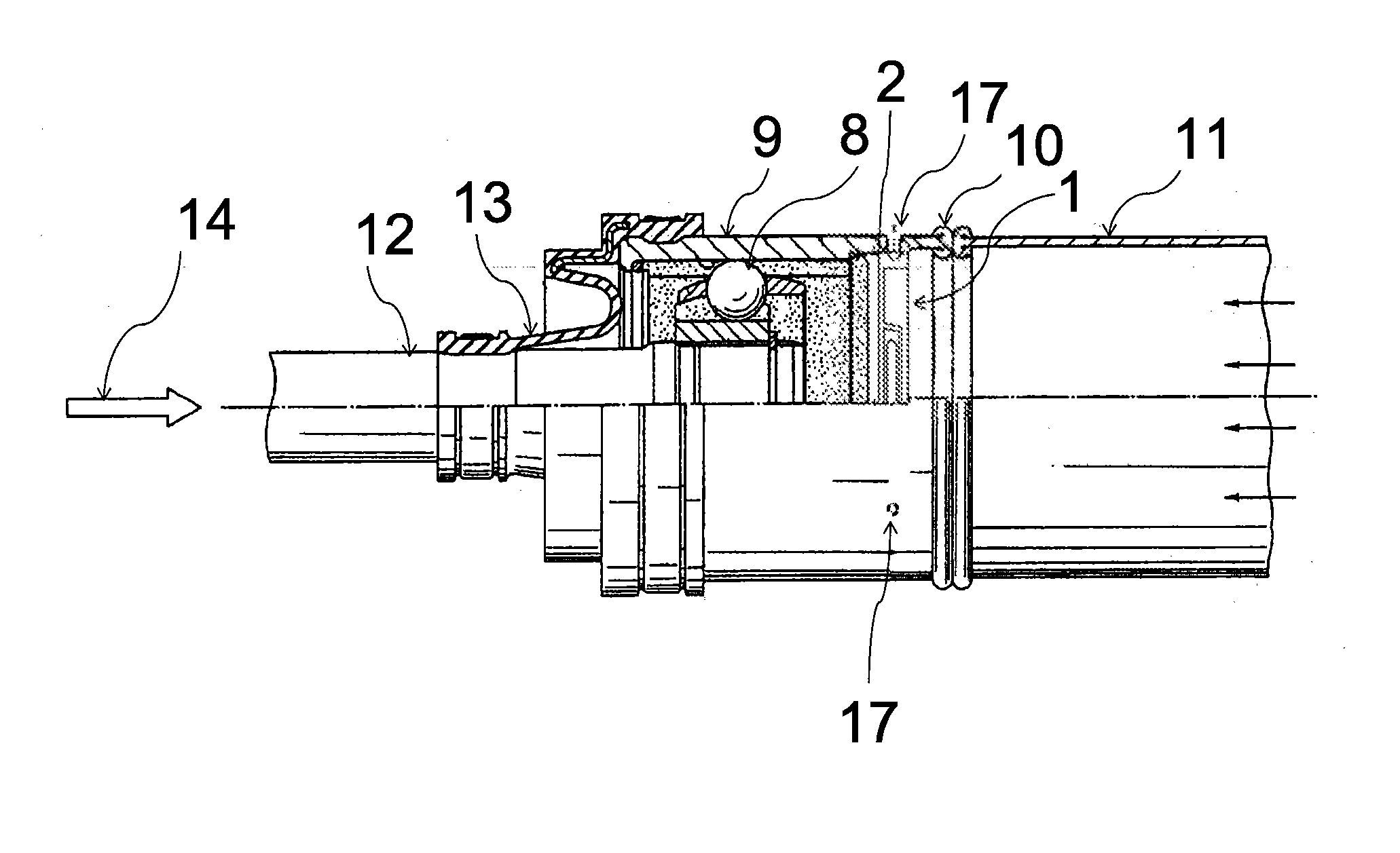
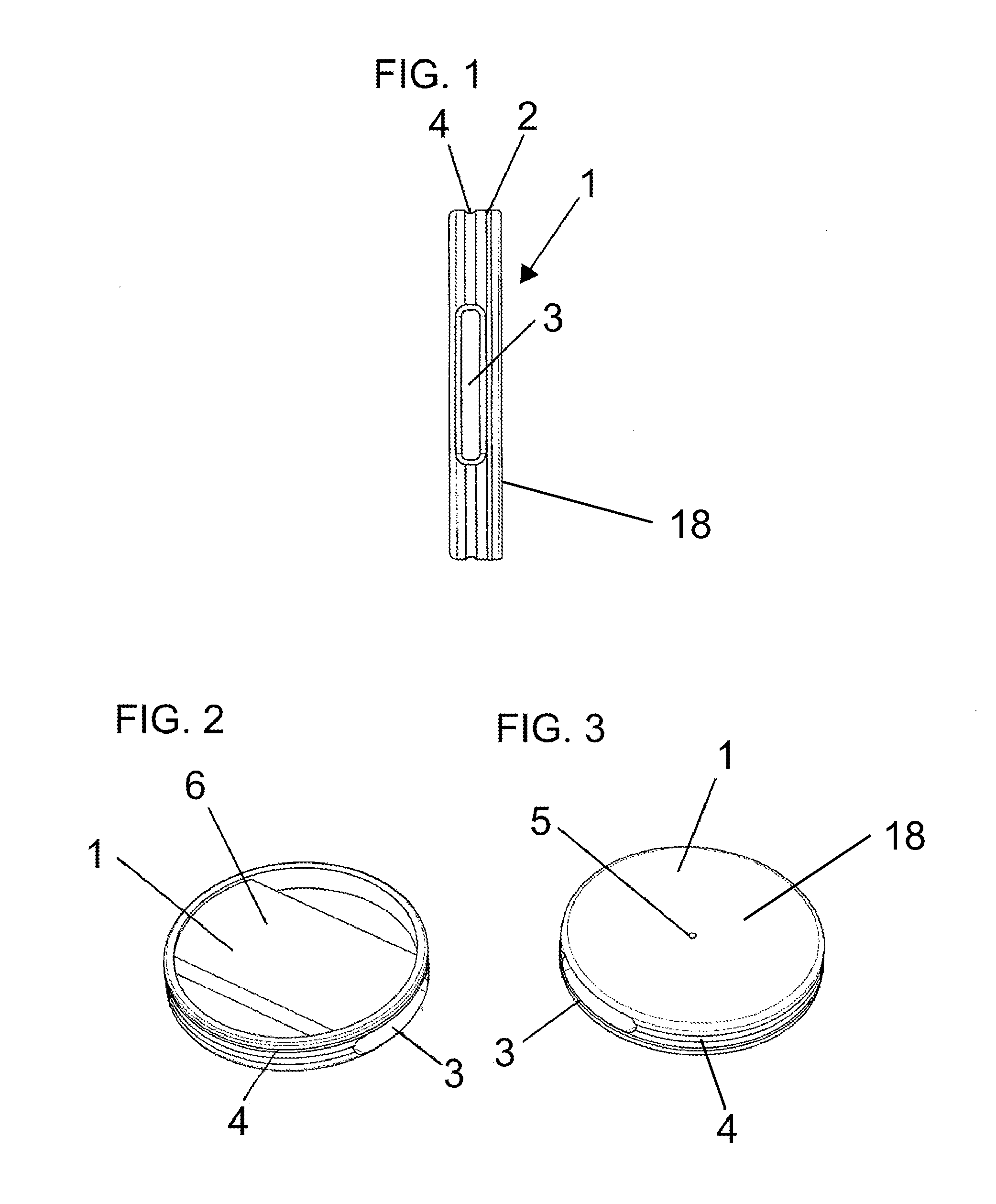
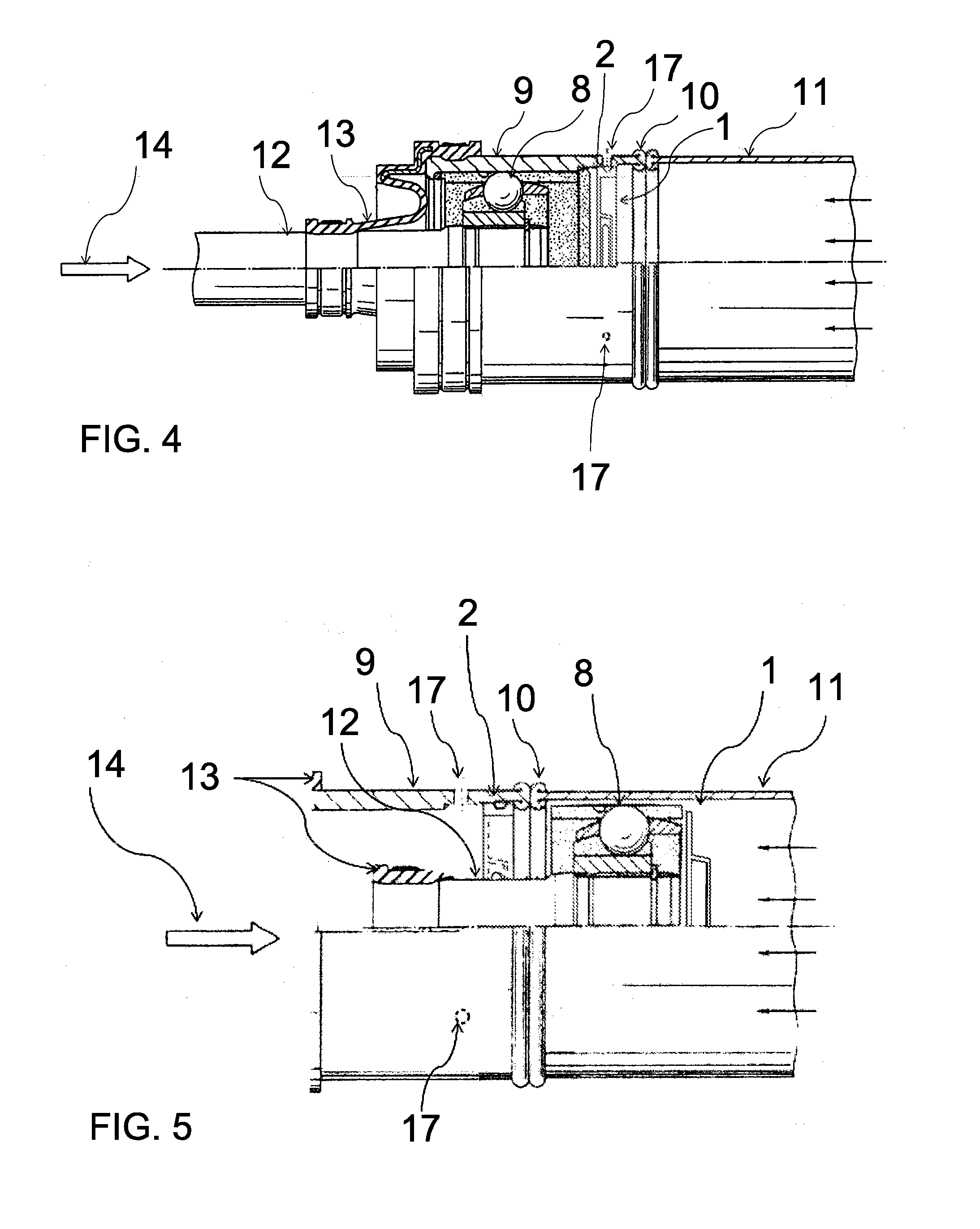
[0023]Referring to FIGS. 1 through 3, a first exemplary embodiment of a grease retention and vent cap 1 has a rim 2 dimensioned to be placed and retained in an outer race 9 of a CVJ. As shown, CVJ has a counter-bored region for receiving cap 1. Other embodiments (not shown) can provide an inside diameter surface for retaining cap 1 adjacent to the CVJ. Retaining the rim 2 in the outer race 9 may be accomplished by a slight radial annular indent placed on a corresponding annular protrusion in the outer race 9.

[0024]Axially adjacent to the rim 2 is an axial area forming a hollow chamber 3 that extends radially across the entire width of the cap 1. The hollow chamber 3 is open at both radial ends and terminates in an annular groove 4 that extends around the entire circumference of the cap 1. An axial vent hole 5 is located centrally in cap wall 18 tha...


PUM


Abstract

Disclosed is a cap that will act as a grease retention feature and venting system, while allowing crash optimization of a propeller shaft with a plunging constant velocity joint. The cap is located between a constant velocity joint and a tube of the propeller shaft system. The cap includes: a rim sealed against the inner diameter of the constant velocity joint, an interior vent chamber, a vent hole facing the interior components of the constant velocity joint and leading to the vent chamber, and an annular radial groove along the entire circumference connected to the vent chamber. The outer race has a hole perpendicular to the joint axis to complete venting to the atmosphere. In the event of a vehicle crash, the constant velocity internal joint components contact the device, causing the device to dislodge from its fixed position, contact the friction weld curls and fracture at a determined load.

Description

TECHNICAL FIELD OF THE INVENTION[0001]The present invention relates to a motor vehicle propeller shaft assembly and a constant velocity joint (CVJ) cap of such an assembly.BACKGROUND OF THE INVENTION[0002]For safety reasons, propeller shaft assemblies for motor vehicles which are oriented longitudinally with constant velocity joints are typically designed with a shock absorption capability during telescopically collapse of the shaft assembly in the event of a frontal impact. These assemblies also need proper sealing against lubricant leakage on the one hand and a venting system on the other hand. All these requirements make the construction of a propeller shaft assembly complex.SUMMARY OF THE INVENTION[0003]The present invention simplifies the propeller shaft assembly by providing a cap inserted into or abutting the outer race of a constant velocity joint (CVJ) that enables both proper sealing and venting without interfering with the energy absorption capability of the assembly.[000...

Claims


Application Information

Patent Timeline
Patent Type & Authority Applications(United States)
IPC IPC(8): F16D3/84
CPCF16D3/227F16D3/84F16D2300/06F16D3/843Y10S277/928Y10S464/906
Inventor KETCHEL, BRADLEYKATKE, CHRISDOUGHERTY, KRISTYNEDWARDS, KRYSTIL
Owner NTN BEARING CORP OF AMERICA
Why Eureka
Try Eureka