Fire sensor

a technology of fire sensor and sensor body, which is applied in the field of fire sensors, can solve the problems of differential fire heat sensor and difficult to achieve a reduction in sensor size, and achieve the effect of enhancing detection sensitivity to a hot airflow

Inactive Publication Date: 2006-03-14
HOCHIKI CORP
View PDF16 Cites 5 Cited by
  • Summary
  • Abstract
  • Description
  • Claims
  • Application Information

AI Technical Summary

Benefits of technology

[0015]With the above-described structure of the fire sensor of the present invention, the heat sensing portion, which comprises the baseplate and the temperature detecting element, is flat in shape and it is therefore easy to reduce the thickness and size of the fire sensor.
[0035]The heat sensing circuit may also constitute a bridge circuit which includes a parallel connection of two transistors collector-connected to the low-temperature detecting portion and a parallel connection of two transistors collector-connected to the high-temperature detecting portions, in order to obtain a differential output that is proportional to a temperature difference between the high-temperature detecting portion and the low-temperature detecting portion. In this case, a change in the base-emitter voltage Vbe of each of the two transistors connected to the low-temperature detecting portion and high-temperature detecting portions is detected and therefore a stable operation with respect to power source voltage fluctuations and external noise can be assured.
[0044]With this arrangement, if the outer cover is exposed to a hot airflow generated by a fire, the hot airflow is collected to the heat sensing portion by the plate fins. Therefore, detection sensitivity to a hot airflow is enhanced.

Problems solved by technology

The above-described fire sensors, however, have the following problem.
Thus, it is fairly difficult to achieve a reduction in sensor size.
Such differential fire heat sensors, however, have the following problems.
However, since the two thermistors 83a, 83b are in a positional relationship that is asymmetrical in a horizontal direction, there is a problem that sensitivity (magnitude of the temperature difference) will greatly depend on the direction of a hot airflow.
However, because the sensing elements S and S′ are disposed in close proximity to each other, there is a problem that the temperature difference therebetween is small.
If the sensing element S is disposed away from the sensing element S′ to obtain a great temperature difference, sensitivity (magnitude of the temperature difference) will depend on the direction of a hot airflow and the sensor will be increased in size and cost.

Method used


Image

  • Fire sensor
  • Fire sensor
  • Fire sensor

Examples


first embodiment

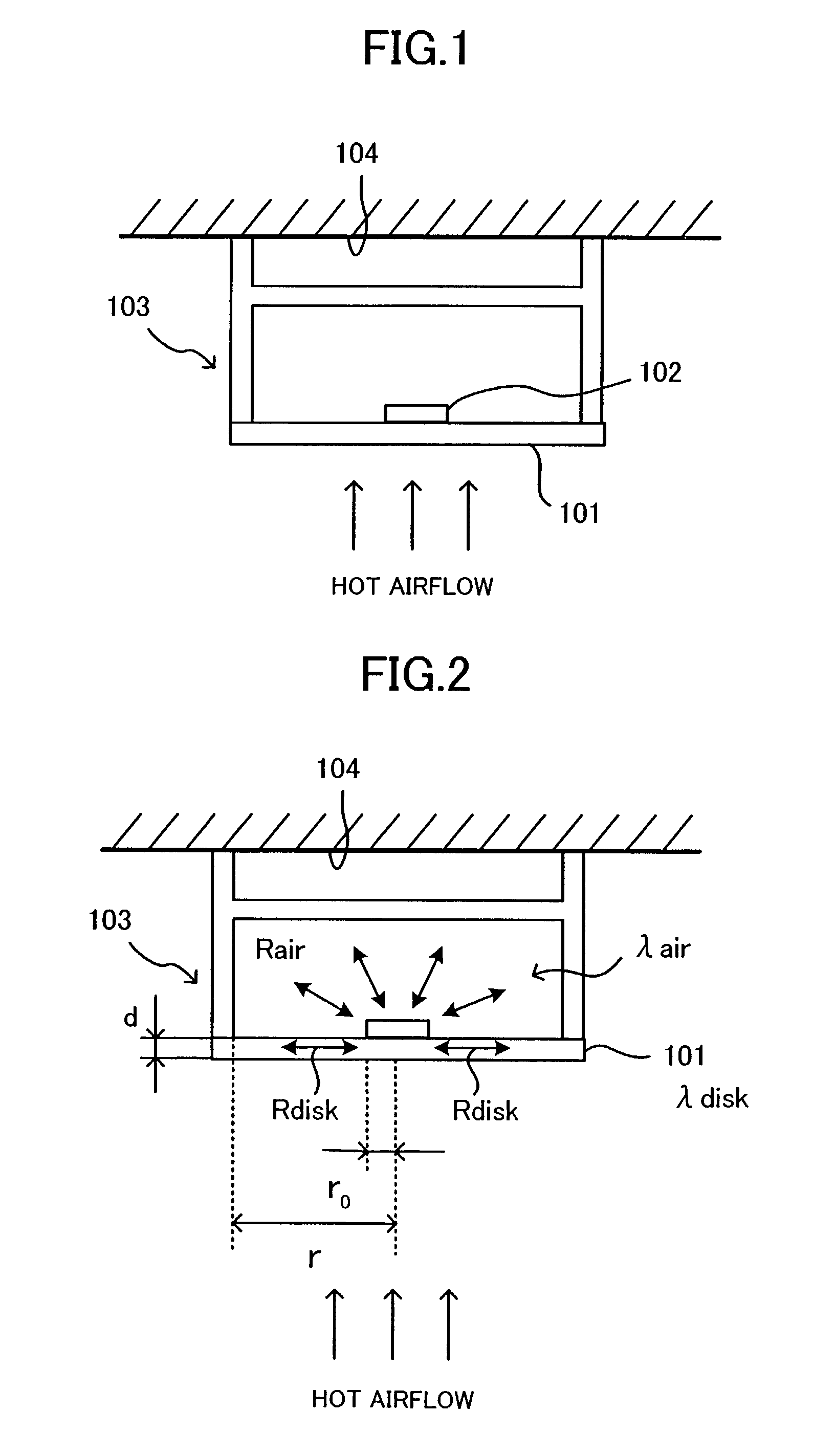
[0130]Referring to FIG. 1, there is depicted a fire sensor constructed in accordance with the present invention. The fire sensor includes a baseplate 101, a temperature detecting element 102, and a sensor main body 103 which serves as a protective case. The outside of the baseplate 101 serves as a heat sensing surface. The temperature detecting element 102 is installed on the central portion of the inside of the baseplate 101 so that it does not contact the sensor main body 103. That is, the temperature detecting element 102 thermally contacts with the inside of the baseplate 101 to detect the temperature of the baseplate 101.

[0131]The sensor main body 103 contacts the radially end portion of the inside surface of the baseplate 101 and forms a closed space between itself and the baseplate 101. The temperature detecting element 102 is confined within the closed space.

[0132]The baseplate 101, temperature detecting element 102, and sensor main body 103 meet the following conditions. In...

eleventh embodiment

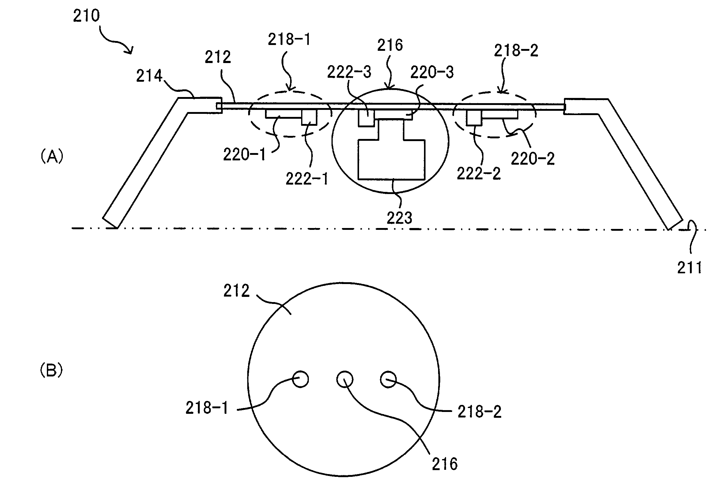
[0186]If the two high-temperature detecting portions 218-1, 218-2 are arranged at positions of axial symmetry with respect to the low-temperature detecting portion 216, as in FIG. 17, differential heat sensing can be performed without being influenced by the direction of a hot airflow generated by a fire.

[0187]Referring to FIG. 18, a heat conduction path in the fire heat sensor 210 of the eleventh embodiment shown in FIG. 17 is represented by an electrical equivalent circuit. The heat collectors 220-1 to 220-3, the heat accumulator 223, and the fixing member 212 are connected with one another through thermal resistors R. The heat collector 223 can be considered a thermal capacitor C. The thermal resistor lower R (lower heat resistance) between the heat accumulator 223 and the heat collector 220-3 is small and the remaining thermal resistors higher R (higher heat resistance) are large. With this construction, the first heat collector 220-1 and the second heat collector 220-2 are arra...

second embodiment

[0244]Referring to FIG. 35, there is depicted a fire heat sensor constructed in accordance with a twenty-second embodiment of the present invention. This embodiment is characterized in that it includes a single high-temperature detecting portion and two low-temperature detecting portions.

[0245]In FIG. 35A, a high-temperature detecting portion 218 is disposed at the center of a fixing member 212, and low-temperature detecting portions 216-1, 216-2 are disposed at positions of axial symmetry across the high-temperature detecting portion 218. Each detecting portion on the fixing member 212 is disposed as shown in FIG. 32, for example. The low-temperature detecting portions 216-1, 216-2 are connected to heat accumulators 223-1, 223-2.

[0246]A heat sensing circuit in this case which performs differential heat sensing is shown in FIG. 35B. That is, a first temperature-difference detecting portion 224-1 detects a first temperature difference ΔT1 between the temperature Th detected by the hi...


PUM

PropertyMeasurementUnit
thicknessaaaaaaaaaa
thicknessaaaaaaaaaa
thicknessaaaaaaaaaa

Abstract

A fire sensor comprising a baseplate, a temperature detecting element, and a protective case. The baseplate has an outside surface which serves as a heat sensing surface which is exposed to a hot airflow generated by a fire. The temperature detecting element thermally contacts with the inside surface of the baseplate to detect the temperature of the baseplate. The protective case contacts with the radially outer portion of the inside surface of the baseplate to form a hermetically sealed space between itself and the baseplate. The temperature detecting element is confined within the hermetically sealed space. The baseplate has the temperature detecting element in approximately the central portion of the inside surface thereof and also has a shape and a material which meet the condition that the product of the thickness and heat conductivity of the baseplate is 1.1×10⁻⁴ (W / K) or less.

Description

BACKGROUND OF THE INVENTION[0001]1. Field of the Invention[0002]The present invention relates generally to a fire sensor, and more particularly to a fire sensor that detects temperature changes in a hot airflow generated by a fire, using a temperature detecting element.[0003]2. Description of the Related Art[0004]A prior art fire sensor, for detecting temperature changes in a hot airflow generated by a fire, is shown in FIG. 56 by way of example (Japanese Utility Model Laid-Open Publication No. SHO55-150490). This fire sensor includes a sensor main body 51 with a circuit board 55 incorporated therein, a protective case 52 made of metal and protruding from the sensor main body 51, and a temperature detecting element 53 housed in the protective case 52. In addition to these components, the fire sensor further includes a heat collecting plate 54 mounted on the tip end of the protective case 52 for purposes of accelerating the speed of a temperature response to a hot airflow generated b...

Claims


Application Information

Patent Timeline
Patent Type & Authority Patents(United States)
IPC IPC(8): G08B17/00G01K3/00G01K7/00G08B23/00G08B17/06
CPCG08B17/06
Inventor MAYUSUMI, KARIYAMAUCHI, YUKIOSHIMA, HIROSHI
Owner HOCHIKI CORP
Why Eureka
Try Eureka