Method for continuous-path control

a technology of path control and path control, applied in the direction of electric programme control, program control, instruments, etc., can solve the problems of poor dynamics and impairment of achieve the effects of improving surface quality, improving machining efficiency, and increasing the surface quality of the machined workpi

Inactive Publication Date: 2006-03-14
DR JOHANNES HEIDENHAIN GMBH
View PDF11 Cites 35 Cited by
  • Summary
  • Abstract
  • Description
  • Claims
  • Application Information

AI Technical Summary

Benefits of technology

[0009]According to an exemplary embodiment of the present invention, a separate velocity control may be performed for angle axes and linear axes. For example, this is achieved by using softer filters for the rounding of the velocity profiles of the angle axes than for the rounding of the velocity profiles of the linear axes. Smaller accelerations (and higher derivatives of the velocity profiles) thereby occur in the angle axes, the deviations in the closed-loop control circuit of the angle axes become smaller, which means the surface quality of the machined workpiece may increase. To nevertheless maintain the necessary path fidelity, the RTCP unit must control a compensation movement in the linear axes such that the engagement point of the tool on the workpiece does not change compared to a synchronous velocity control. Given suitable parameterization, the effect of the improved surface quality may be shifted totally or partially in favor of a higher machining velocity.

Problems solved by technology

A disadvantage in the method of continuous-path control described is that, in machine tools having a plurality of axes, in each case the axes having the poorest dynamics (thus, for example, the lowest maximum acceleration) predefine the velocity control.
This results in impairment of the surface quality of the machined workpiece, since in this case, the angle axis fully utilizes the path deviation allowed to it.

Method used


Image

  • Method for continuous-path control
  • Method for continuous-path control
  • Method for continuous-path control

Examples


Embodiment Construction

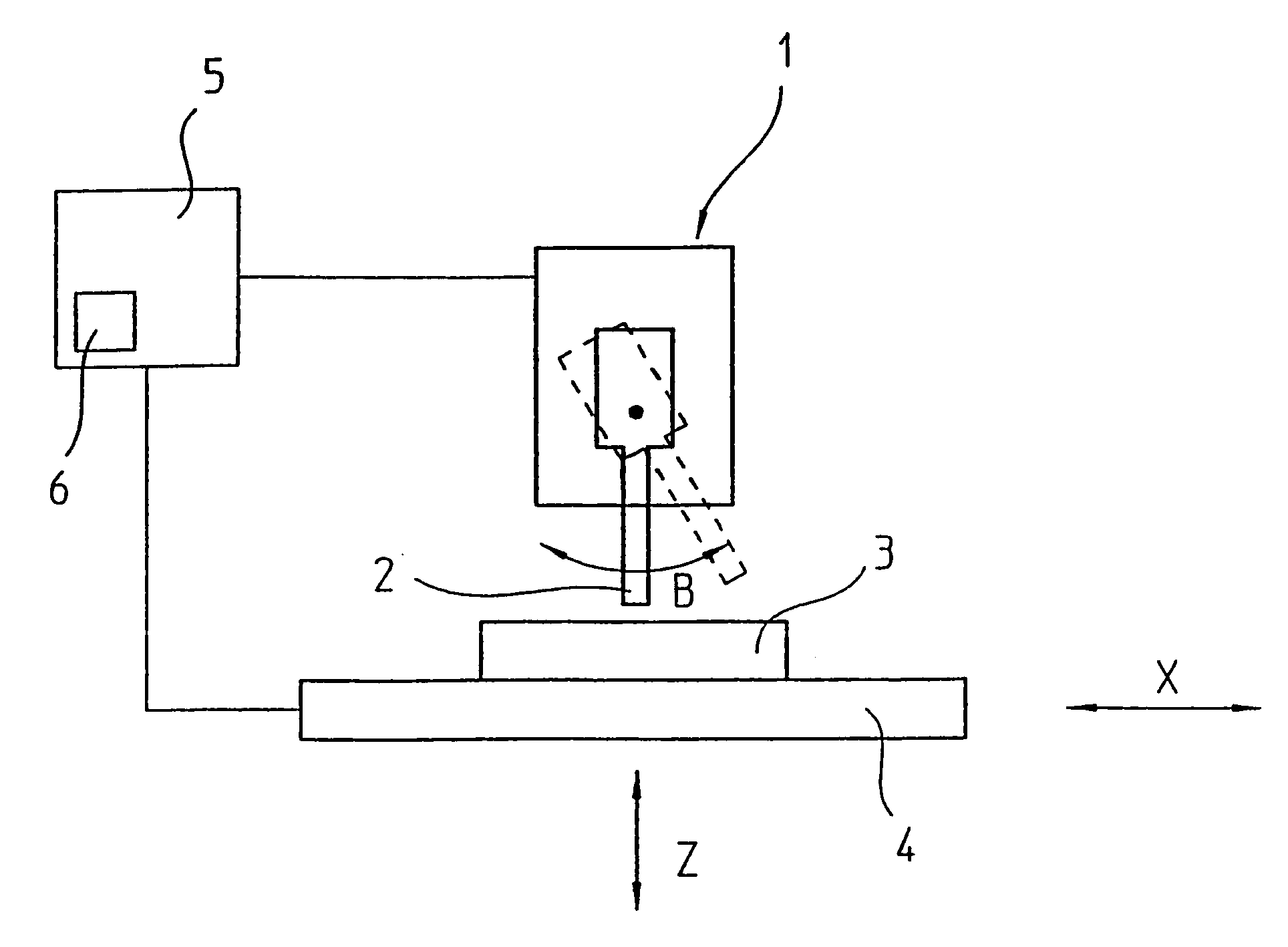
[0014]FIG. 1 shows a machine tool 1 having a tool 2. A workpiece 3 is mounted on a machining table 4. Workpiece 3 and tool 2 are movable relative to each other in several axes. Thus, linear axes in the X-direction and Z-direction are shown in the drawing; a third linear axis in the Y-direction is normal to the drawing plane. In a 5-axis milling machine, there are also two angle axes, of which the B-axis is shown in FIG. 1. Tool 2 is able to swivel about the direction of the Y-axis. A second angle axis A is obtained when machining table 4 is able to be tilted about the X-axis. Axes X, Y, Z, A, B are controlled by a numerical control 5 which, for example, is able to execute a parts program or receive and carry out individual commands by the machine-tool operator.

[0015]FIG. 1 illustrates that a movement of tool 2 about angle axis B causes the tip of tool 2 to shift with respect to workpiece 3. To simplify the programming of the machining of a workpiece in a plurality of axes X, Y, Z, A...


PUM


Abstract

In a method for continuous-path control in at least two linear axes and at least one angle axis, the movement of a tool relative to a workpiece is predefined by a parts program for a numerical control. The velocity control in the numerical control is performed separately for the linear axes and the angle axes. Deviations in the movement between the tool and the workpiece resulting due to the separate velocity control may be corrected by compensation movements of the linear axes. The separate velocity control for the linear axes and the angle axes may be achieved by rounding the velocity profiles in the angle axes more significantly than the velocity profiles in the linear axes. A measure for the rounding for velocity profiles may be predefined separately for the angle axes and the linear axes.

Description

FIELD OF THE INVENTION[0001]The present invention relates to a method for continuous-path control.BACKGROUND INFORMATION[0002]Numerical controls are used in modern machine tools to control the positioning and movement of tools relative to a workpiece. To machine a workpiece in accordance with a setpoint selection, it may be necessary to move the tool relative to the workpiece on paths established beforehand. Therefore, one also speaks of a continuous-path control. The desired paths are determined in a parts program that is executed by the numerical control. In so doing, the numerical control converts the geometrical statements of the parts program into statements for the positional control of the different axes of the machine tool.[0003]In such a parts program, for example, any tool paths as needed are approximated by interpolation points (also known as support points), between which the continuous-path control linearly interpolates. In modern machine tools such as a 5-axis milling ...

Claims


Application Information

Patent Timeline
Patent Type & Authority Patents(United States)
IPC IPC(8): G05B19/25G05B19/416
CPCG05B19/416G05B2219/34042G05B2219/43056G05B2219/43057G05B2219/50353G05B2219/45145G05B2219/49243G05B2219/50297G05B2219/43105
Inventor HAUNERDINGER, JOSEFZACEK, JOHANNBRADER, ANTONRAUTH, MICHAEL
Owner DR JOHANNES HEIDENHAIN GMBH
Why Eureka
Try Eureka