Modulation using discrete amplitude adjustment and dual digital delay lines

a digital delay and discrete amplitude adjustment technology, applied in the field of telecommunication systems, can solve the problems of large power consumption of modulators of this form, limited binary digital systems, and inability to achieve multilevel systems. to achieve the effect of facilitating this action

Active Publication Date: 2006-03-14
VECIMA NETWORKS
View PDF11 Cites 8 Cited by
  • Summary
  • Abstract
  • Description
  • Claims
  • Application Information

AI Technical Summary

Benefits of technology

[0050]The invention may provide one or more of the following advantages:
[0053]It removes all digital to analog converters (DACs) from the modulation process. Another advantage is it also provides a novel method for amplitude and phase modulation which does not require post modulation amplification. Removal of the DACs and amplifier results in a significant power reduction compared to the conventional techniques.

Problems solved by technology

Binary digital systems are limited in that they can only represent a one bit symbol (0 or 1) at any given time.
However, binary digital systems are not as practical as multilevel systems since digital transmission is notoriously wasteful of RF bandwidth, and regulatory authorities usually require a minimum bandwidth efficiency.
Due to its requirements for digital to analog conversion and linear power amplification before transmission, modulators of this form typically consume lots of power.

Method used


Image

  • Modulation using discrete amplitude adjustment and dual digital delay lines
  • Modulation using discrete amplitude adjustment and dual digital delay lines
  • Modulation using discrete amplitude adjustment and dual digital delay lines

Examples


Embodiment Construction

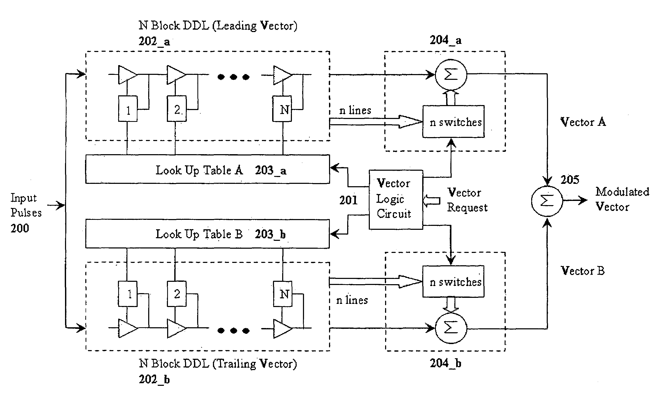
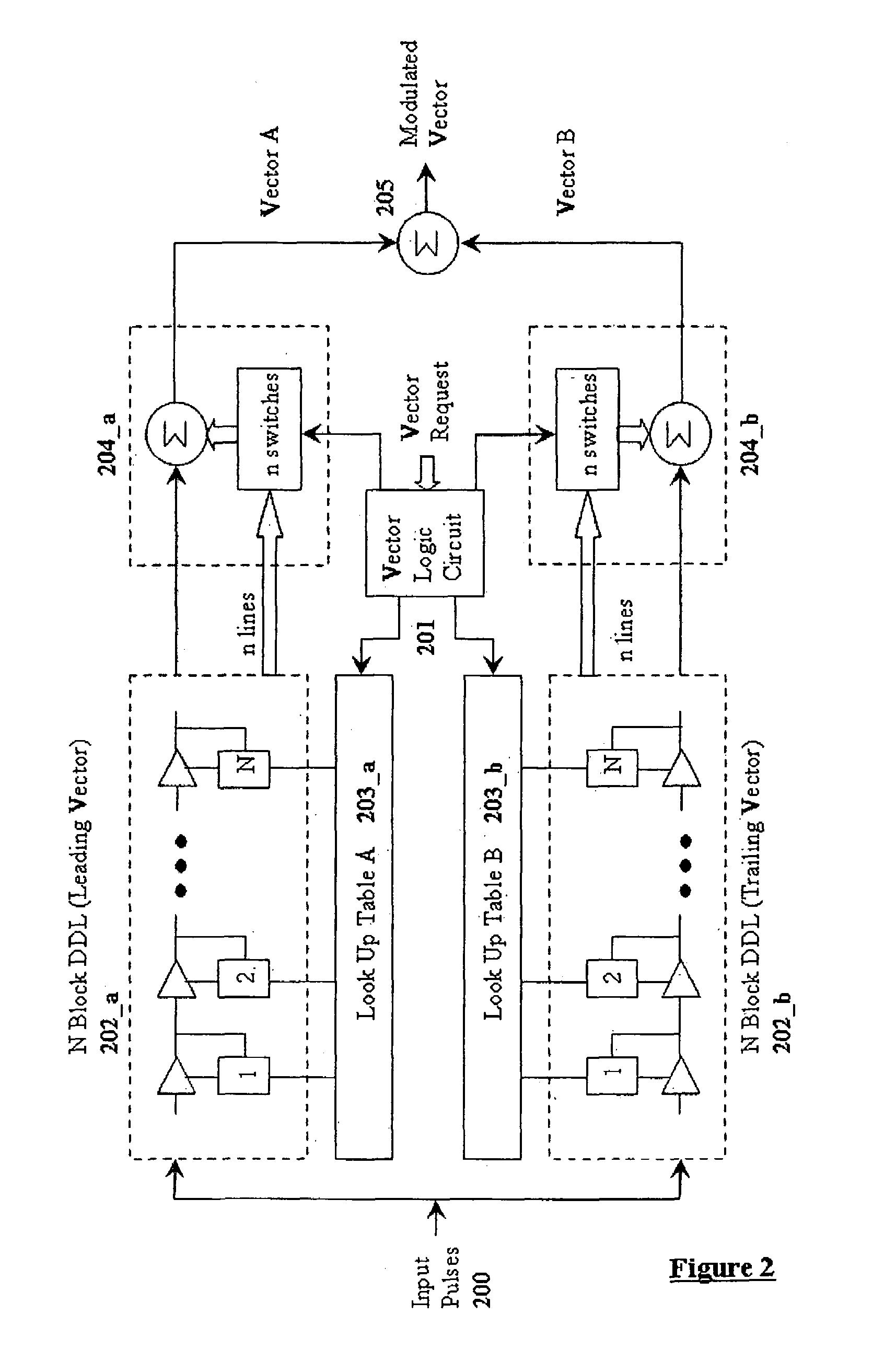
[0060]This invention synthesizes a vector with the desired amplitude and phase using two vectors that have dynamically controlled phases and discretely controlled magnitudes. FIG. 2 illustrates a block diagram of the invention. The invention consists of six major blocks; input pulses 200, a vector logic circuit 201, two digital delay lines 202, two lookup tables 203, two discrete amplitude control circuits 204, and a signal combiner 205.

[0061]The vector logic circuit 201 is supplied with digital data corresponding to the desired magnitude and phase of the output vector. Once the data has been received the logic circuit determines the phase and magnitude of the two vectors needed to generate the desired output vector. The vector logic circuit 201 determines the phase of each vector by using the following assumptions:

[0062]Both vectors will have the same magnitude.

[0063]Each vector will be equidistant, radially, from the resultant vector.

[0064]Having defined the vectors in the above m...


PUM


Abstract

The present invention provides a means to implement amplitude and phase modulation digitally and directly at an RF frequency that benefits from high output power without the use of amplifiers. This is accomplished by the combination of two varying amplitude and phase vectors. A reference oscillator produces a carrier signal, which is supplied to two digital delay lines composed of a sequence of delay banks. The delay lines are controlled by lookup tables that are updated by the vector control circuit, used to determine the delay of each digital delay line. The output of each delay line is multiplexed to a switching bank which is also controlled by the vector control circuit. The output of the switching bank, in combination with a summer, is used to produce discrete amplitude adjustment of the vector. The delay of the lines and the summation adjustment are set in such a way as to produce two vectors with the desired phase shift and magnitude the summation of these two vectors produces a resultant vector with the desired phase and amplitude characteristics.

Description

[0001]This application claims priority under 35 U.S.C. 119 from Provisional Application Ser. No. 60 / 525,118 filed Nov. 28th, 2003.[0002]This application is related to an application filed simultaneously with this application by the same inventors and entitled AMPLITUDE AND PHASE MODULATION USING DUAL DIGITAL DELAY VECTORS the disclosure of which is incorporated herein by reference.FIELD OF THE INVENTION[0003]This invention relates generally to telecommunication systems. The present invention relates more specifically to data transmission using analog signals, more specifically, to a unique method for providing amplitude and phase modulation of a signal using multiple summations of the outputs of dual digital delay lines.BACKGROUND OF THE INVENTION[0004]The following references may be relevant to the present invention:[0005]U.S. Pat. No. 5,329,259 Stengel, “Efficient Amplitude / Phase Modulation Amplifier”[0006]U.S. Pat. No. 5,612,651 Chethik, “Modulating Array QAM Transmitter”[0007]U....

Claims


Application Information

Patent Timeline
Patent Type & Authority Patents(United States)
IPC IPC(8): H03K7/10H03C5/00H04L27/36
CPCH04L27/365
Inventor HARRON, GERALDTUCKER, JASON T.KUMAR, SURINDER
Owner VECIMA NETWORKS
Why Eureka
Try Eureka