
Optical heterodyne detection in optical cavity ringdown spectroscopy

a technology of optical cavity and ringdown spectroscopy, which is applied in the field of optical absorption spectroscopy, can solve the problems of large optical loss in the system, unsuitable for many applications, and inability to detect at greater sensitivities, and achieve enhanced detection sensitivity of optical cavity ringdown spectroscopy, facilitating environmental, agricultural, clinical and industrial monitoring applications, and enhancing the effect of sensitivity

Inactive Publication Date: 2006-03-14
MACQUARIE RES
View PDF11 Cites 145 Cited by
  • Summary
  • Abstract
  • Description
  • Claims
  • Application Information

AI Technical Summary

Benefits of technology

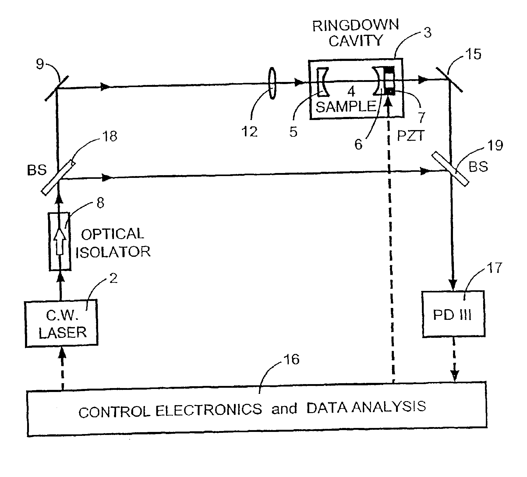
[0095]In accordance with the present invention there is provided a means for coupling and decoupling the light / radiation to and from the optical cavity. Such means is typically provided by a piezoelectric translator (PZT) operated to provide movement (preferably continuous) of at least one of the reflectors / mirrors contained in the optical cavity cell so as to vary the length of the optical cavity. The duration of the movement is suitably rapid with respect to the ringdown time. The light / radiation can be most efficiently coupled into the optical cavity under optical resonance conditions, where the round-trip optical cavity length is an integer multiple of the wavelength of the light / radiation. Suitably the reflector / mirror is moved rapidly by mounting the reflector / mirror on a cylindrical piezoelectric translator (PZT) with its sweep controlled by a triangular or saw-tooth or other complex form of ramp voltage operated by an electronic control circuit. Suitable optical cavity length shifts are of the order of 1 nm to 1 μm and are typically applied on a time scale that is shorter than the ringdown time of the optical cavity so as to shift the ringdown cavity on and off resonance, as ringdown cavities have high finesse (typically>104). The PZT sweep amplitude typically approximates one wavelength of the light in the optical cavity, thereby ensuring that one strong optical cavity resonance occurs in each PZT sweep half-cycle. Optical energy is built up and stored in the optical cavity as any of its modes moves into resonance with the wavelength of the light, and the optical cavity then transmits more light. The decay of light energy that is built up and stored in the optical cavity during the short resonance interval is observable after the optical cavity has moved off resonance, because the input light is effectively blocked by the highly reflective optical cavity reflectors / mirrors during the (relatively long) off resonance interval. The decay of light energy is gradual with a ringdown time constant τ that depends on the reflector / mirror reflectivity and the optical absorption of the optical medium in the optical cavity.
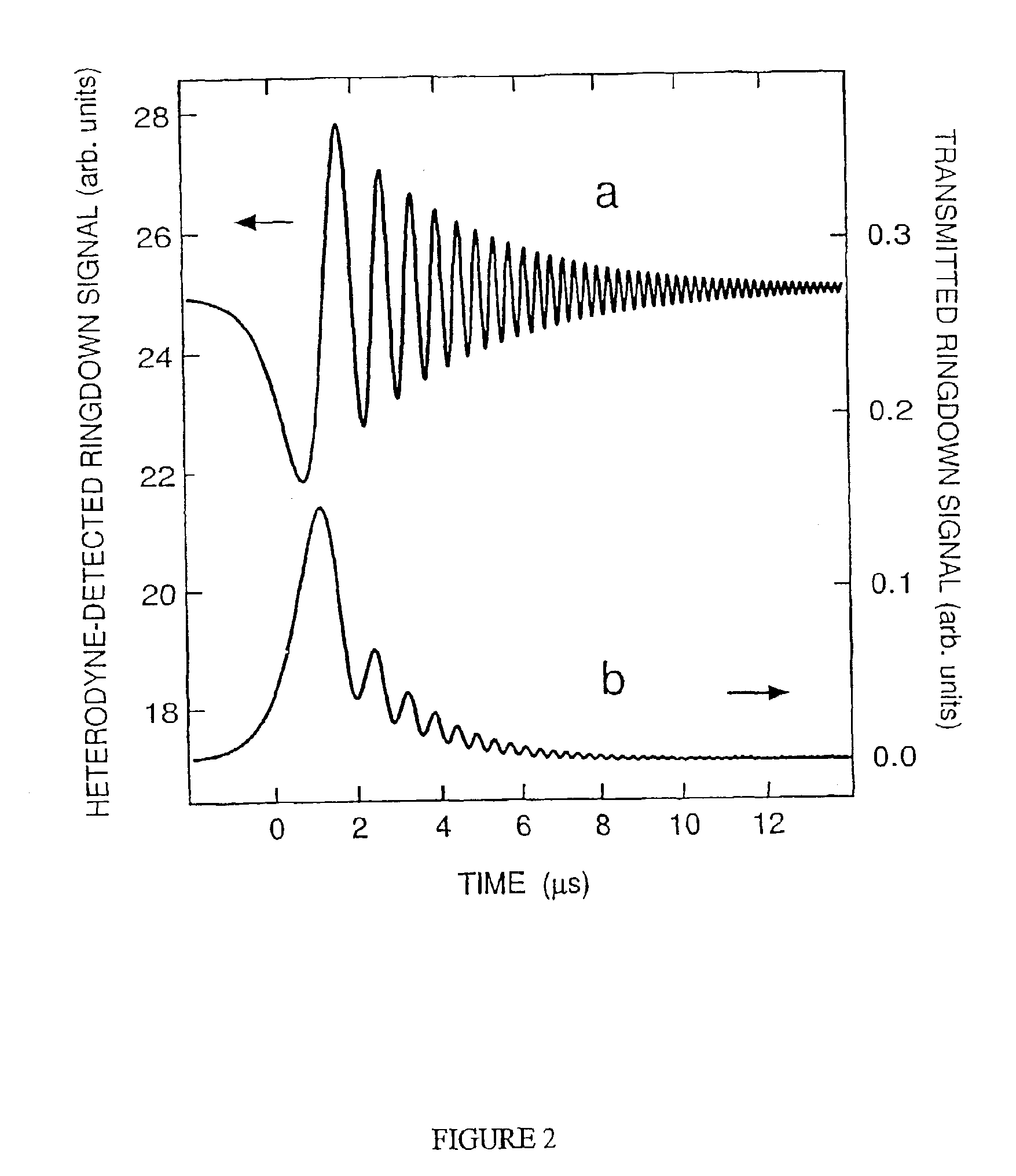
[0108]By means of the present invention it is possible to use a rapidly swept or stepped optical cavity in a novel approach to optical cavity ringdown spectroscopy (CRDS) suitably with a continuous-wave (cw) laser. The frequency of the optical light / radiation trapped inside the optical cavity is suitably shifted by moving at least one optical cavity mirror / reflector. The frequency-shifted optical cavity ringdown light / radiation is then suitably combined efficiently with the original light / radiation enabling generation of an optical heterodyne signal. (An alternative view of this process treats the entire optical cavity with its moving mirror / reflector as a single active optical element with resonant properties depending on the mirror / reflector movement.) Measurement of cw-CRDS signals by this optical heterodyne approach enhances the detection sensitivity by several orders of magnitude. The resonance properties of a swept optical cavity also simplify cw-CRDS in that they eliminate the need for a fast optical switch and avoid locking of the optical cavity length and laser wavelength to each other although optical switches may still be desirable in some applications. By use of the apparatus and methods of the invention it is possible to obtain ultra-sensitive, high-resolution, accurate CRD spectroscopy with relatively simple, inexpensive, compact apparatus suitable for use in the field or at industrial sites or in clinical situations.

Problems solved by technology

Detection at greater sensitivities however is not readily attainable with current CRDS systems where problems such as optical feedback, noise present in detection electronics and large optical losses in the systems are present.
Further many of the prior art apparatus require the use of large pulsed lasers which are not amenable to portability and are therefore unsuitable in many applications.

Method used


Image

  • Optical heterodyne detection in optical cavity ringdown spectroscopy
  • Optical heterodyne detection in optical cavity ringdown spectroscopy
  • Optical heterodyne detection in optical cavity ringdown spectroscopy

Examples


example 1

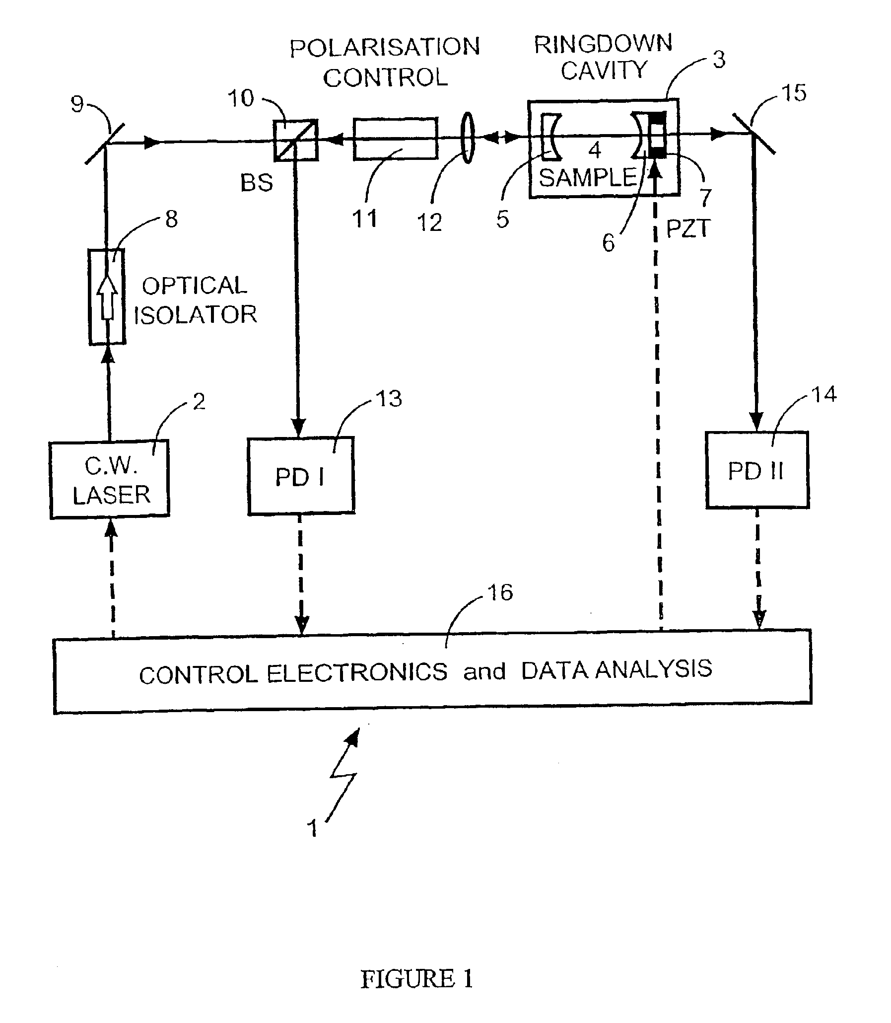
[0134]The rovibrational optical absorption band of carbon dioxide gas (CO2) at ˜1.53 μm was examined spectroscopically using the optical-heterodyne detection continuous wave CRDS method of the present invention with a rapidly swept optical cavity and using the apparatus shown in FIG. 1. The apparatus used included a cw TDL tunable diode laser (New Focus model 6262 / 6200; ˜5 mW single-mode output; tunable over 1.50-1.59 μm with ˜1-MHz optical bandwidth), a piezoelectrically controlled ringdown optical cavity, two amplified photodetectors 13 and 14 (InGaAs; 125-MHz bandwidth), a digital oscilloscope (Tektronix TDS3054; 500-MHz bandwidth), and control electronics with IEEE-488 computer interface. The TDL beam traversed an optical isolator (−80 dB) and was mode-matched to the ringdown cavity by a lens of 50-cm focal-length. A polarisation control unit (a 45° Faraday rotator which also augmented optical isolation) enabled a polarising beam splitter (PBS) to direct the backward-propagating...

example 2

[0154]We now consider a second detailed example to illustrate the application of multi-wavelength optical heterodyne cw-CRDS by means of apparatus of the form depicted in FIGS. 11, 12 and 15. The example concerns simultaneous detection of the gas-phase species carbon monoxide (CO) and carbon dioxide (CO2). Measurement of the CO / CO2 ratio in exhaled air can be used to diagnose certain medical conditions. Likewise, the ratio of these two species is a key indicator of combustion processes in industry and the environment, where incomplete combustion or inefficient conversion of hydrocarbon fiels results in higher relative concentration of CO. Spectroscopic, laser-based detection of the CO / CO2 ratio in combustion effluent streams (e.g., industrial smokestacks) offers the prospect of real-time combustion process control and / or environmental monitoring of air quality. For instance, this has already been recognised and implemented in the steel industry, where a tunable mid-infrared diode la...


PUM

PropertyMeasurementUnit
optical bandwidthaaaaaaaaaa
distancesaaaaaaaaaa
distancesaaaaaaaaaa

Abstract

The disclosure relates to optical heterodyne detection cavity ringdown spectroscopy. In one aspect the disclosure relates to an optical system comprising a ringdown cavity cell defining a resonant optical cavity, means for directing coherent light selected from the group consisting of continuous or quasi-continuous light into said optical cavity, means for altering the resonant optical cavity so as to generate a frequency shift of the coherent light in the optical cavity, means for coupling said coherent light into the optical cavity and means for decoupling the frequency shifted coherent light out of said optical cavity, means for optically combining said decoupled frequency shifted coherent light with another portion of coherent light not in optical communication with the optical cavity and means for optical heterodyne detection of the intensity of said combined light. A method for optical detection is also described as well as methods and apparatus for detecting a parameter of a sample.

Description

[0001]This is the U.S. national phase of International Application No. PCT / AU01 / 00834 filed Jul. 12, 2001, the entire disclosure of which is incorporated herein by reference.TECHNICAL FIELD[0002]The present invention relates to optical absorption spectroscopy and in particular is directed to a method and apparatus for optical heterodyne detection using an optical ringdown cavity cell.BACKGROUND OF THE INVENTION[0003]The detection of trace and weakly absorbing gas-phase species is of importance in scientific, industrial, medical, agricultural and environmental spectroscopic sensing applications. In recent years optical cavity ringdown laser absorption spectroscopy (CRDS) has become a new analytical technique for determination of such trace concentrations. The technique is simple, quick, versatile and an accurate way to acquire weak optical absorption spectra, the method typically able to make optical absorption measurements with sensitivities of the order of 10−7 per cm of sample. Ge...

Claims


Application Information

Patent Timeline
Patent Type & Authority Patents(United States)
IPC IPC(8): G01B9/02G01J3/42G01N21/39H01S3/106
CPCG01J3/42G01N21/39H01S3/1062G01N2021/391
Inventor ORR, BRIAN J.HE, YABAI
Owner MACQUARIE RES
Learn More