Forward converter with controlled reset

a forward converter and control technology, applied in the direction of efficient power electronics conversion, electric variable regulation, instruments, etc., can solve the problems of transformers that cannot be used in the same way, transformers that are complicated, and the voltage spikes across the main switch at each turn o

Inactive Publication Date: 2006-03-14
DET INT HLDG LTD
View PDF11 Cites 11 Cited by
  • Summary
  • Abstract
  • Description
  • Claims
  • Application Information

AI Technical Summary

Benefits of technology

[0030]The control of the reset switch is readily accomplished, in the case of the preferred and exemplary embodiment, by a simple voltage divider coupling the reset winding to the control electrode of the semiconductor switching device serving as the reset switch. By choosing the appropriate reset capacitor value, the fluxin the power transformer is substantially symmetrical about zero. In this way the BH curve of the transformer is well utilized. In the exemplary preferred embodiment described below, the inventive device is broadly a power device having a power transformer and a reset capacitive element that releases energy to a first winding of the power transformer to reset the power transformer. Under the control of a reset switching means such as a semiconductor switching device that connects the reset capacitive element in current conducting relation to the first winding, the switching device is itself under the control of a reset winding and means that connects the reset winding to the reset switching means. The opening and closing of the reset switching means under the control of the reset winding causes transformer-resetting current flow between the reset capacitive element and the first winding of the power transformer. In this way, the leakage and magnetizing inductance energy in the transformer is recycled and spiking across the main switch is avoided. Again, current from the reset winding through a pair of resistors forming a voltage divider permits the control of the reset switch through choice of the ratio of the voltage divider resistors. In this specific preferred embodiment, the reset winding activates the reset switching means upon the collapse of a magnetic field in the core of the power transformer.
[0031]In accordance with the preferred embodiment of the invention the reset voltage is constant. It is easily controlled, e.g. by the likes of the simple divider described, and the reset voltage can be set to accommodate the desired function of the power device. Additional driving and timing circuits for the switch or FET are not required. Leakage and magnetizing inductance energy is recycled. Spikes across the main switch are avoided. During transients the duty cycle can increase without increasing the voltage stress on the main switch. The reset voltage can be also adjusted as a function of the input to maximize the performances and minimize the stress.

Problems solved by technology

Drawbacks of this concept are:a. If leakage inductance energy is not recycled, the result may be voltage spikes across the main switch at each turn off.b. The need for the reset winding well coupled with the primary complicates the transformer.c. The flux density through the power transformer's magnetic core is not symmetrical to zero.
This leads to a poor utilization of the magnetic core.
Drawbacks of this concept are:a. There is high voltage stress on the main switch.b. Fast variation of the duty cycle and Vin will further lead to high voltage stress on the main switch.c. The turn on switching losses will increase due to the full discharge of the reset capacitor on the main switch.
There are also disadvantages:a. During transients (load or line) the voltage across the reset capacitor can reach very high levels, at the same time the flux can reach high levels.
The net result, it is not a good topology for fast dynamic response.b. The primary inductance and the reset capacitor form a resonant circuit, which will oscillate during transients.c. The complexity of driving the reset switch (a MOSFET switch, for example) with just the right timing.

Method used


Image

  • Forward converter with controlled reset
  • Forward converter with controlled reset
  • Forward converter with controlled reset

Examples


Embodiment Construction

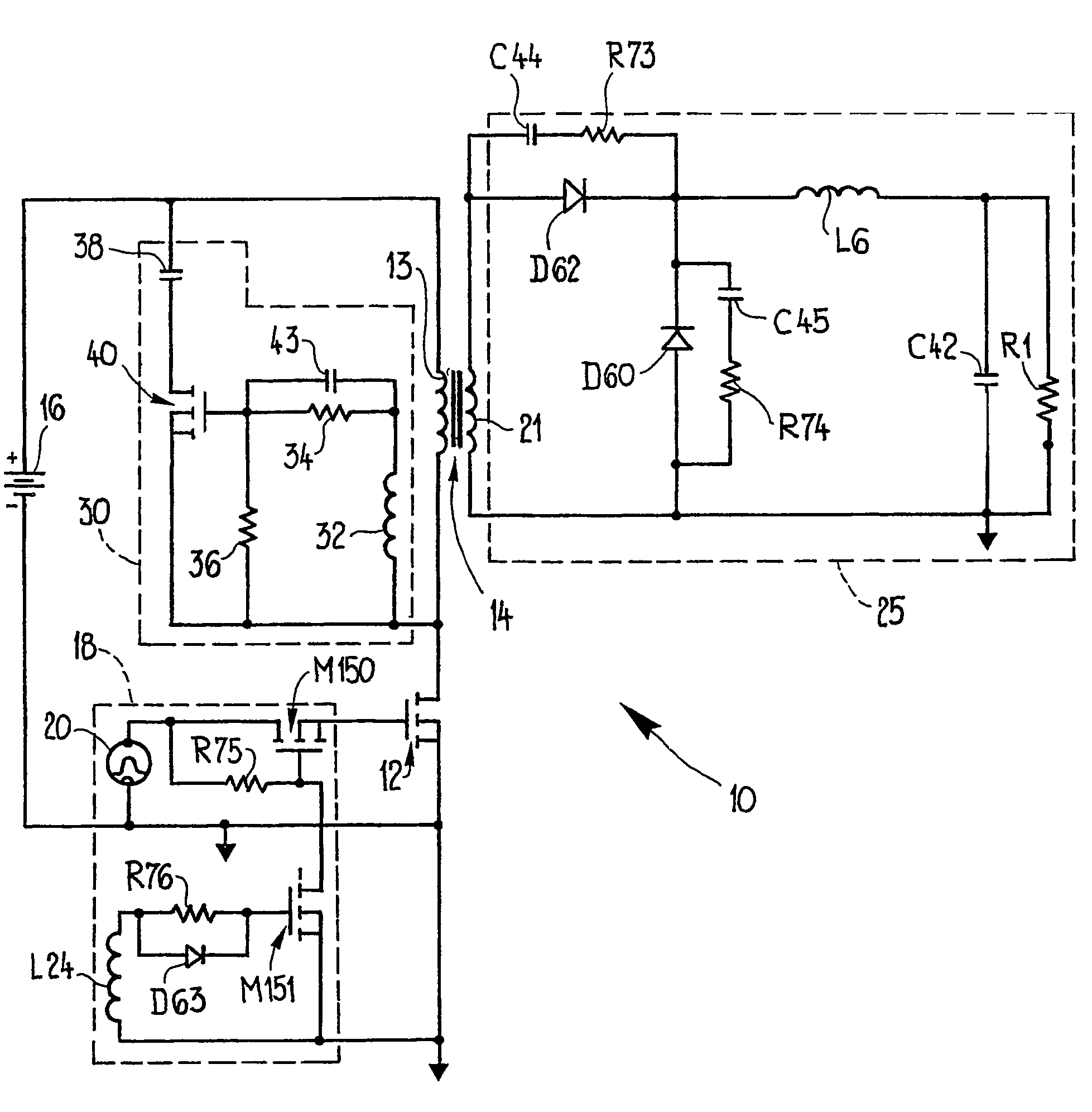
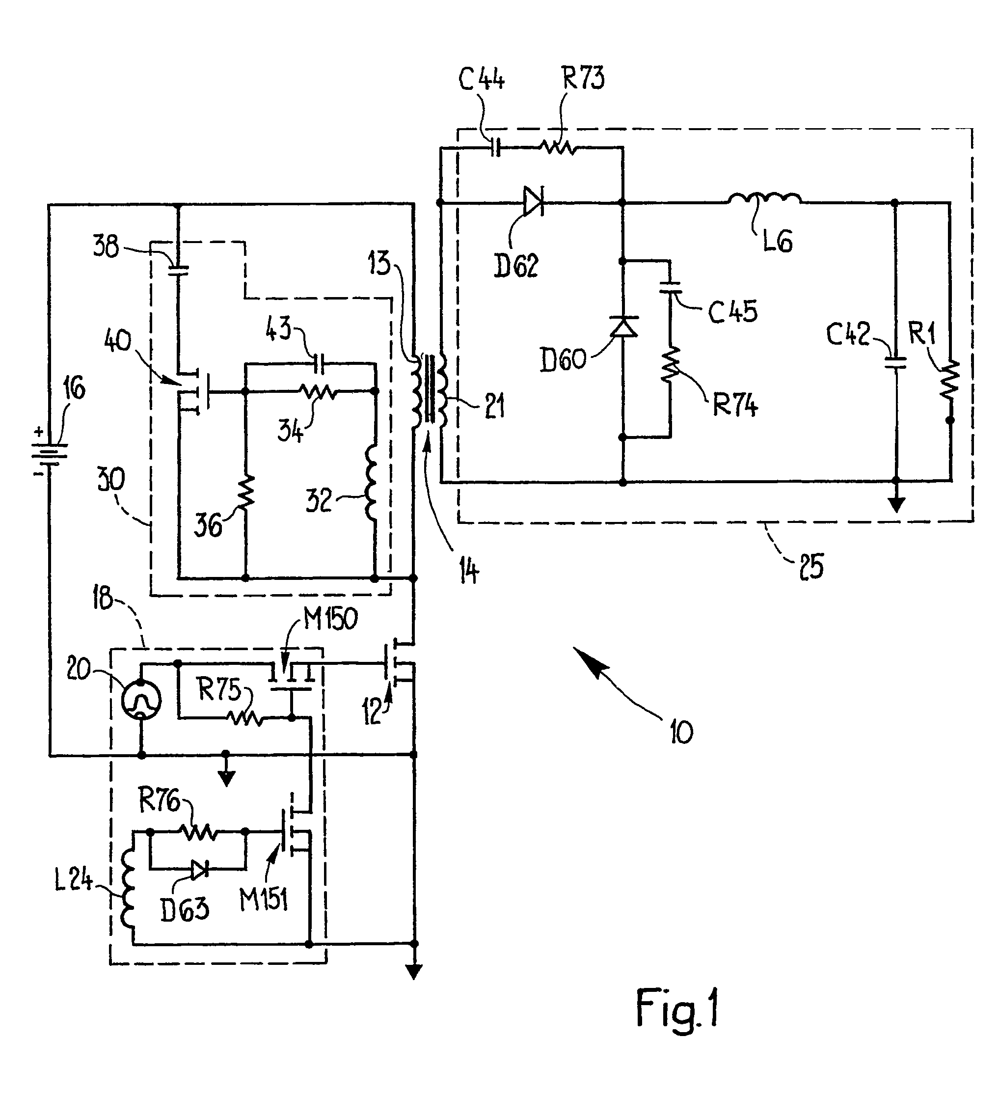
[0037]Turning to FIG. 1, there is shown a forward converter 10 in which a main switch 12 is connected in series with a primary winding 13 of a power transformer 14 and a DC voltage source 16. Opening and closing of the main switch 12, a MOSFET device, is controlled by a switching circuit 18 coupled to the gate of the MOSFET switch. A voltage 20 supplies the input to the control circuit 18. The main switch, MOSFET 12, is opened and closed to interrupt and supply current through the primary winding 13 to generate a voltage across the secondary winding 21 of the power transformer 14. This is applied to a secondary or output circuit 25. The output of the forward converter 10 is applied across a load represented in. FIG. 1 by the resistance R1.

[0038]A reset circuit 30 includes a reset winding 32 wound on the core of the power transformer 14. Across the reset winding 32 a pair of resistors 34 and 36 form a voltage divider. A reset capacitor 38 is connected in series with a reset switch or...


PUM


Abstract

A power device such as a forward converter employing a main switch in series with a power transformer coupling an input, primary circuit and an output, secondary circuit has its transformer reset from a reset capacitor that is switched. Switching of the reset capacitor is effected by a reset switch, preferably a MOSFET, the control electrode of which is driven from a reset winding on the power transformer. Current flow between the reset capacitor and the primary winding resets the transformer. The capacitor can be chosen such that flux density in the transformer core is substantially symmetrical about zero. Leakage and magnetizing conductance energy is recycled. Large spikes are not produced across the main switch.

Description

CROSS REFERENCE TO RELATED APPLICATIONS[0001]Priority is claimed from U.S. provisional patent application Ser. No. 60 / 342,314 of lonel D. Jitaru filed Dec. 21, 2001 entitled “A Forward Converter with Controlled Reset.” That application is incorporated herein by reference in its entirety.TECHNICAL FIELD[0002]This invention relates to transformer reset provisions for a power device and more particularly to a controlled reset for a forward converter using a switched reset capacitance.PRIOR ART[0003]A forward converter typically has a main switch in the primary circuit of a power transformer coupling the input, primary circuit and secondary, output circuit. The resetting of the transformer of a forward converter in the prior art is done in several different ways:[0004]1. The Third Wire Reset[0005]In this technique, a reset winding well coupled with the primary winding of the forward converter's power transformer is used to reset the transformer. The turn ratio between the reset winding ...

Claims


Application Information

Patent Timeline
Patent Type & Authority Patents(United States)
IPC IPC(8): H02M3/335H02M1/34
CPCH02M1/34H02M3/33569Y02B70/1491H02M2001/342Y02B70/10H02M1/342
Inventor JITARU, IONEL D.
Owner DET INT HLDG LTD
Why Eureka
Try Eureka