Apparatus for controlling fuel injection of engine and method thereof

a technology of fuel injection and apparatus, which is applied in the direction of electric control, machines/engines, output power, etc., can solve the problems of inability to inject all of fuel and inability to form a uniform air-fuel mixture in the cylinder, and achieve excellent combustion stability

Active Publication Date: 2006-03-21
HITACHI ASTEMO LTD
View PDF10 Cites 9 Cited by
  • Summary
  • Abstract
  • Description
  • Claims
  • Application Information

AI Technical Summary

Benefits of technology

[0009]It is therefore an object of the present invention to enable to form in a cylinder, a uniform air-fuel mixture with excellent combustion stability, in a condition where a valve lift of an intake valve is low and a valve operating angle thereof is small.

Problems solved by technology

However, if the valve operating angle becomes smaller, since an opening period of the intake valve becomes shorter, it is impossible to inject all of fuel within the opening period of the intake valve, and therefore, sometimes, fuel injection needs to be started before opening timing of the intake valve.
Consequently, there is a problem in that, if the fuel is injected before the opening timing of the intake valve, a uniform air-fuel mixture in the cylinder is not formed.

Method used


Image

  • Apparatus for controlling fuel injection of engine and method thereof
  • Apparatus for controlling fuel injection of engine and method thereof
  • Apparatus for controlling fuel injection of engine and method thereof

Examples


Embodiment Construction

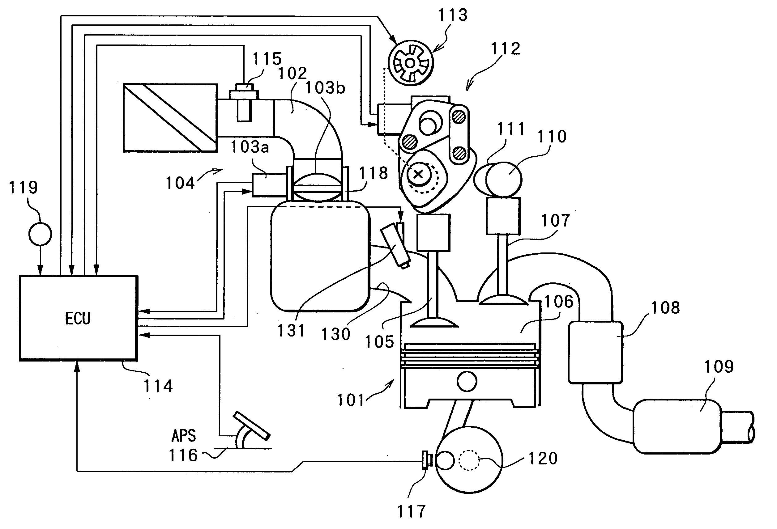
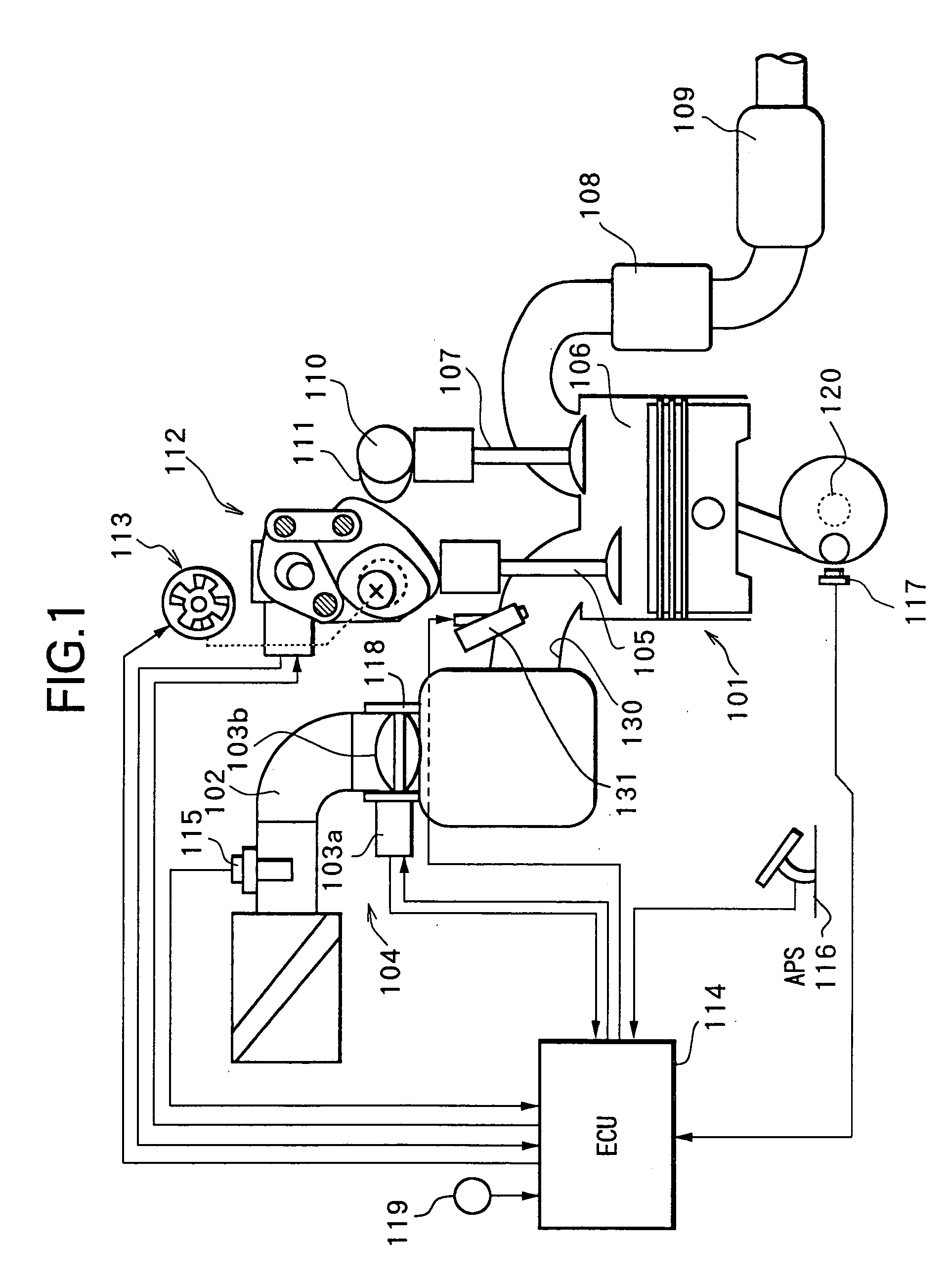
[0030]FIG. 1 shows an engine for vehicle.

[0031]In FIG. 1, an intake passage 102 of an engine 101 is disposed with an electronically controlled throttle 104.

[0032]Electronically controlled throttle 104 is constructed to drive a throttle valve 103b to open and close by a throttle motor 103a.

[0033]Air is sucked into a combustion chamber 106 via electronically controlled throttle 104 and an intake valve 105.

[0034]A combusted exhaust gas is discharged from combustion chamber 106 via an exhaust valve 107, purified by a front catalyst 108 and a rear catalyst 109, and then emitted into the atmosphere.

[0035]Exhaust valve 107 is driven to open and close by a cam 111 axially supported by an exhaust side camshaft 110, while keeping a fixed valve lift and a fixed valve operating angle thereof.

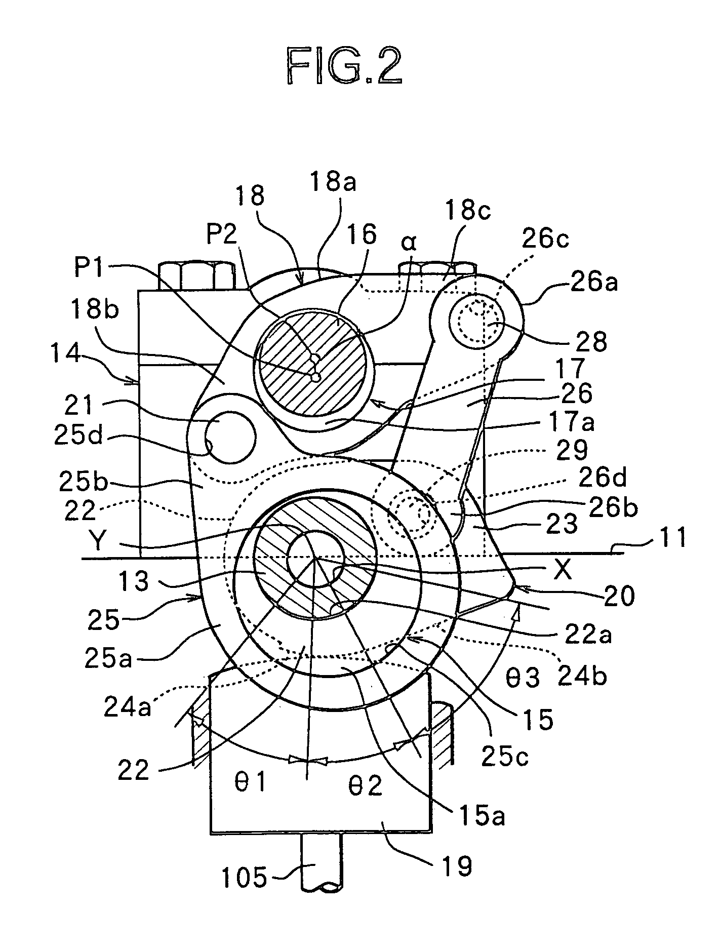
[0036]Intake valve 105 is provided with a VEL (Variable valve Event and Lift) mechanism 112 that performs continuously a variable control of a valve lift together with a valve operating angle, and a VTC (V...


PUM


Abstract

In an engine provided with a variable valve event and lift mechanism that varies a valve lift and a valve operating angle of an intake valve, a pressure of fuel supplied to a fuel injection valve is controlled according to an opening period of the intake valve, which is varied according to the valve operating angle and an engine rotation speed.

Description

FIELD OF THE INVENTION[0001]The present invention relates to an apparatus for controlling fuel injection in an engine provided with a fuel injection valve on the upstream side of an intake valve, and a method thereof.RELATED ART OF THE INVENTION[0002]Heretofore, there has been known a control system in which an operating characteristic of an intake valve is changed so that a target intake air amount of an engine can be obtained (refer to Japanese Unexamined Patent Publication No. 6-272580).[0003]Further, there has also been known a variable valve event and lift mechanism that varies continuously a valve lift of an engine valve together with a valve operating angle thereof (refer to Japanese Unexamined Patent Publication No. 2001-012262)[0004]Here, when a valve lift of an intake valve is controlled by the variable valve event and lift mechanism to adjust an intake air amount of an engine, the valve lift of the intake valve is controlled to be smaller together with a valve operating a...

Claims


Application Information

Patent Timeline
Patent Type & Authority Patents(United States)
IPC IPC(8): F02M51/00F01L1/34F01L1/344F01L1/356F01L13/00F01N13/02F02D13/02F02D41/04F02D41/34F02D43/00F02M37/08F02M69/00F02M69/04
CPCF01L1/3442F01N13/009F02D13/023F02D41/345F02M69/045F01N13/0093F01L13/0026F01L2001/34469F01L2013/0073F01L2201/00F02D2041/001F02D2200/063F02D2250/31Y02T10/44Y02T10/18Y02T10/12Y02T10/40
Inventor SARUWATARI, MASAYUKI
Owner HITACHI ASTEMO LTD
Why Eureka
Try Eureka