
Vacuum valve controller

a valve controller and vacuum valve technology, applied in the direction of sewage draining, liquid handling, transportation and packaging, etc., can solve the problems of difficult to deliver sewage, difficult to achieve vacuum, and hardly developed air lock in the pipe system, so as to achieve easy and inexpensive re-design

Active Publication Date: 2006-03-21
EBARA CORP
View PDF6 Cites 8 Cited by
  • Summary
  • Abstract
  • Description
  • Claims
  • Application Information

AI Technical Summary

Benefits of technology

"The present invention provides a vacuum valve controller that can be easily and inexpensively remodeled when replacing an existing vacuum valve controller. The vacuum valve controller includes a pressure sensor, a vacuum valve opening and closing mechanism, an open-state holding mechanism, and a pressure transmitting mechanism. The pressure sensor converts the water level in a sewage pit into a pressure, and the pressure valve controller opens or closes the vacuum valve based on the pressure variation. The open-state holding mechanism holds the vacuum valve open until air is drawn in through the suction pipe after sewage is drawn in. The pressure transmitting mechanism transmits the pressure upstream of the vacuum valve to the open-state holding mechanism to detect when air is drawn in through the suction pipe. The vacuum valve system includes a vacuum valve, a pressure sensor, a vacuum valve opening and closing mechanism, an open-state holding mechanism, and a pressure transmitting mechanism. The technical effects of the present invention include easy and inexpensive remodeling, improved vacuum control, and efficient sewage pumping."

Problems solved by technology

If the air lock is developed, then the degree of vacuum required to deliver sewage is not achieved at the end of the vacuum sewage pipe 305, making it difficult to deliver sewage.
Therefore, no water hammer occurs, and an air lock is hardly developed in the pipe system.
This modification is highly laborsome and time-consuming.
Therefore, a large replacement expense is required.

Method used


Image

  • Vacuum valve controller
  • Vacuum valve controller
  • Vacuum valve controller

Examples


Embodiment Construction

[0028]A vacuum valve controller according to embodiments of the present invention will be described in detail with reference to the drawings.

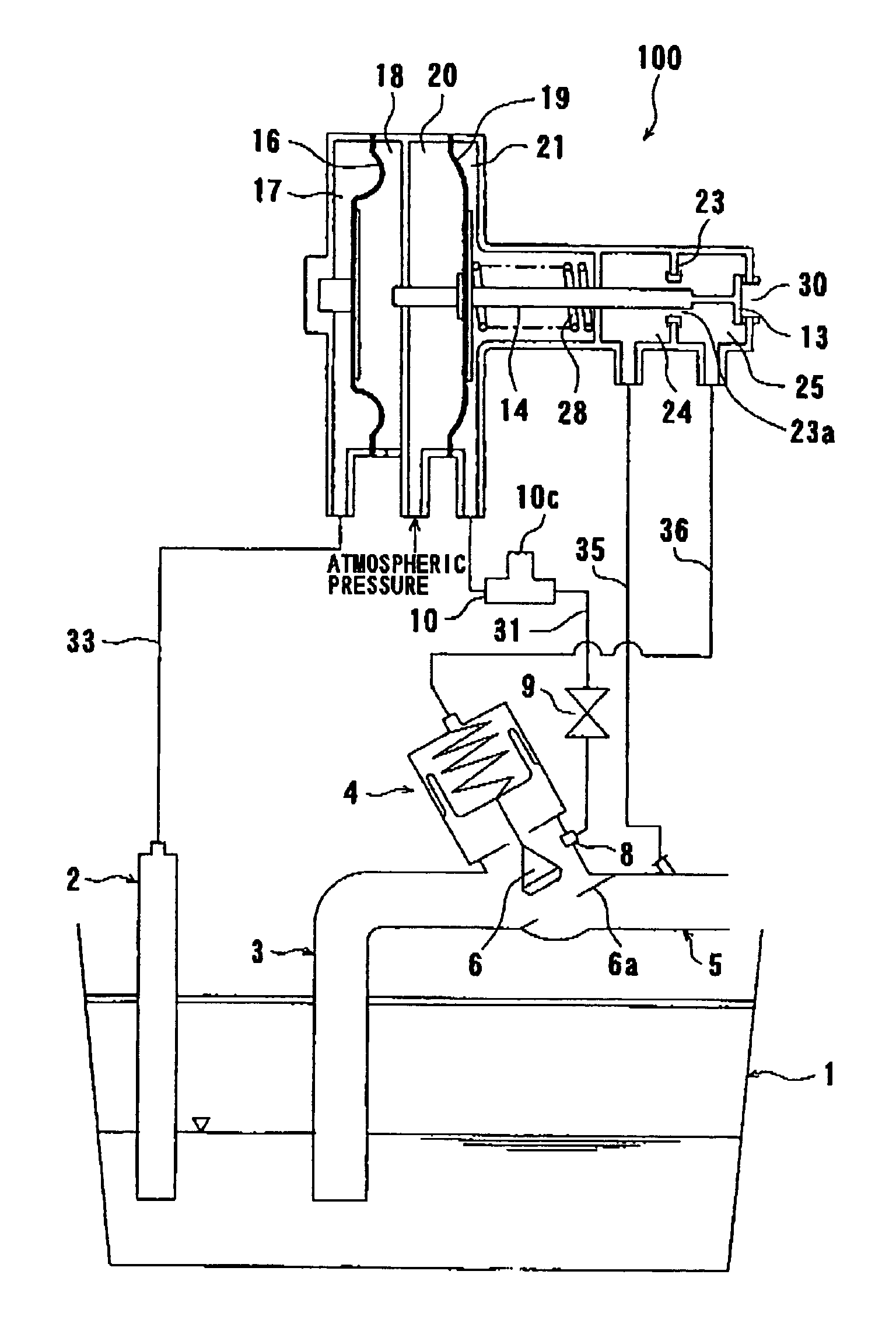
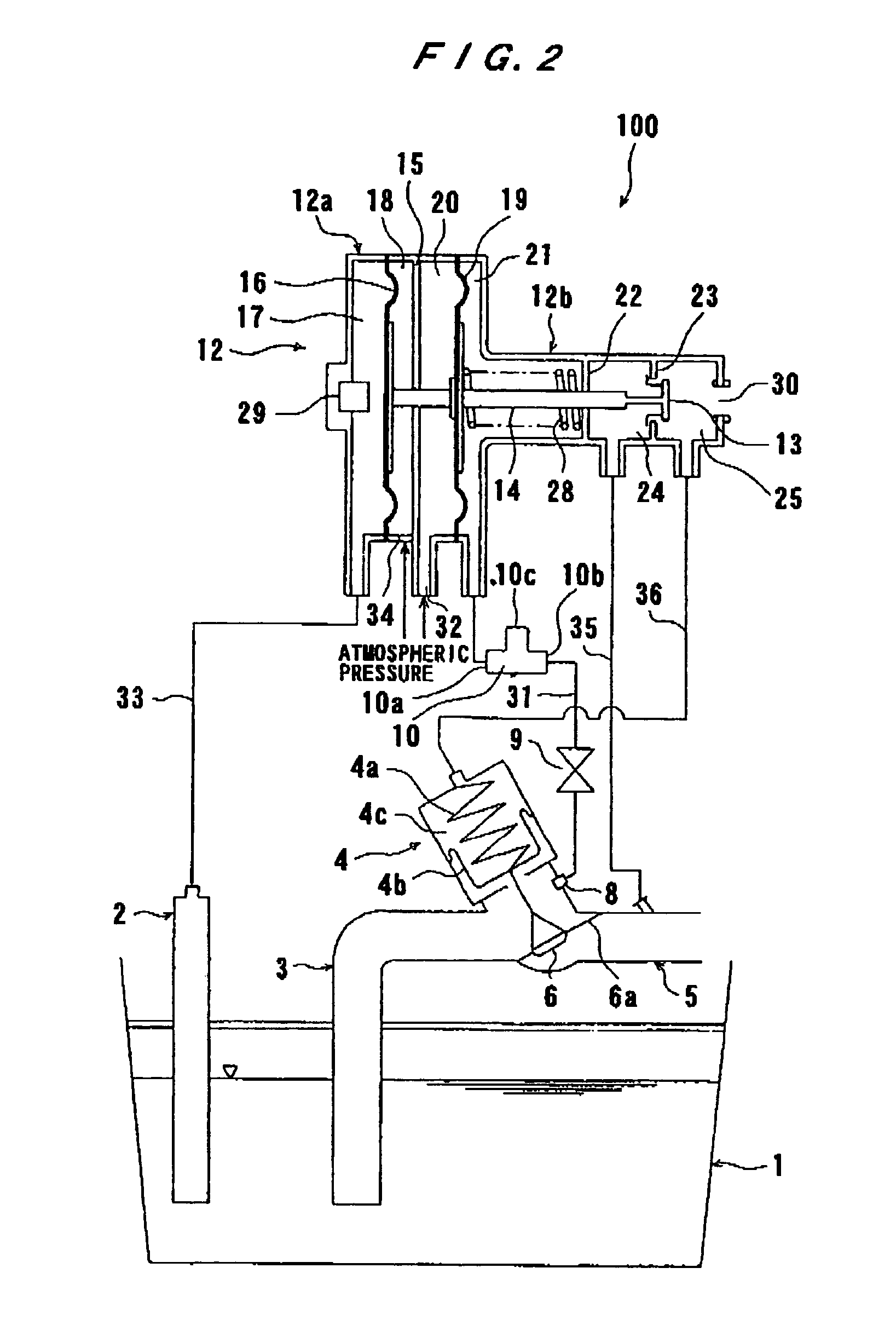
[0029]FIG. 2 is a sectional side view of a vacuum valve controller 100 attached to a vacuum valve 4 according to the present invention. FIG. 3 is an enlarged cross-sectional view of the vacuum valve controller 100. As shown in FIGS. 2 and 3, a suction pipe 3 has a distal end inserted in a sewage pit 1 and an opposite end connected through a vacuum valve 4 to a vacuum sewage pipe 5 (vacuum system) communicating with a vacuum tank (not shown). The vacuum valve 4 is controlled so as to be opened and closed by the vacuum valve controller 100.

[0030]The vacuum valve 4 comprises a piston chamber 4c, a diaphragm 4b disposed in the piston chamber 4c, a spring 4a disposed in the piston chamber 4c for biasing the diaphragm 4b, and a valve disc (valve element) 6 disposed outside of the piston chamber 4c and being movable for opening and closing the vacuum ...


PUM


Abstract

The present invention provides a vacuum valve controller for opening and closing a vacuum valve mounted on an end of a pipe of a vacuum system that is part of a vacuum sewage system. A vacuum valve controller includes a pressure sensor for converting a water level of sewage in a sewage pit into a pressure, a vacuum valve opening and closing mechanism for opening and closing the vacuum valve according to a variation of the pressure detected by the pressure sensor, an open-state holding mechanism for holding the vacuum valve open until air is drawn in through the suction pipe after sewage is drawn in through a suction pipe, and a pressure transmitting mechanism for transmitting a pressure upstream of the vacuum valve in the suction pipe to the open-state holding mechanism to detect when air is drawn in through the suction pipe.

Description

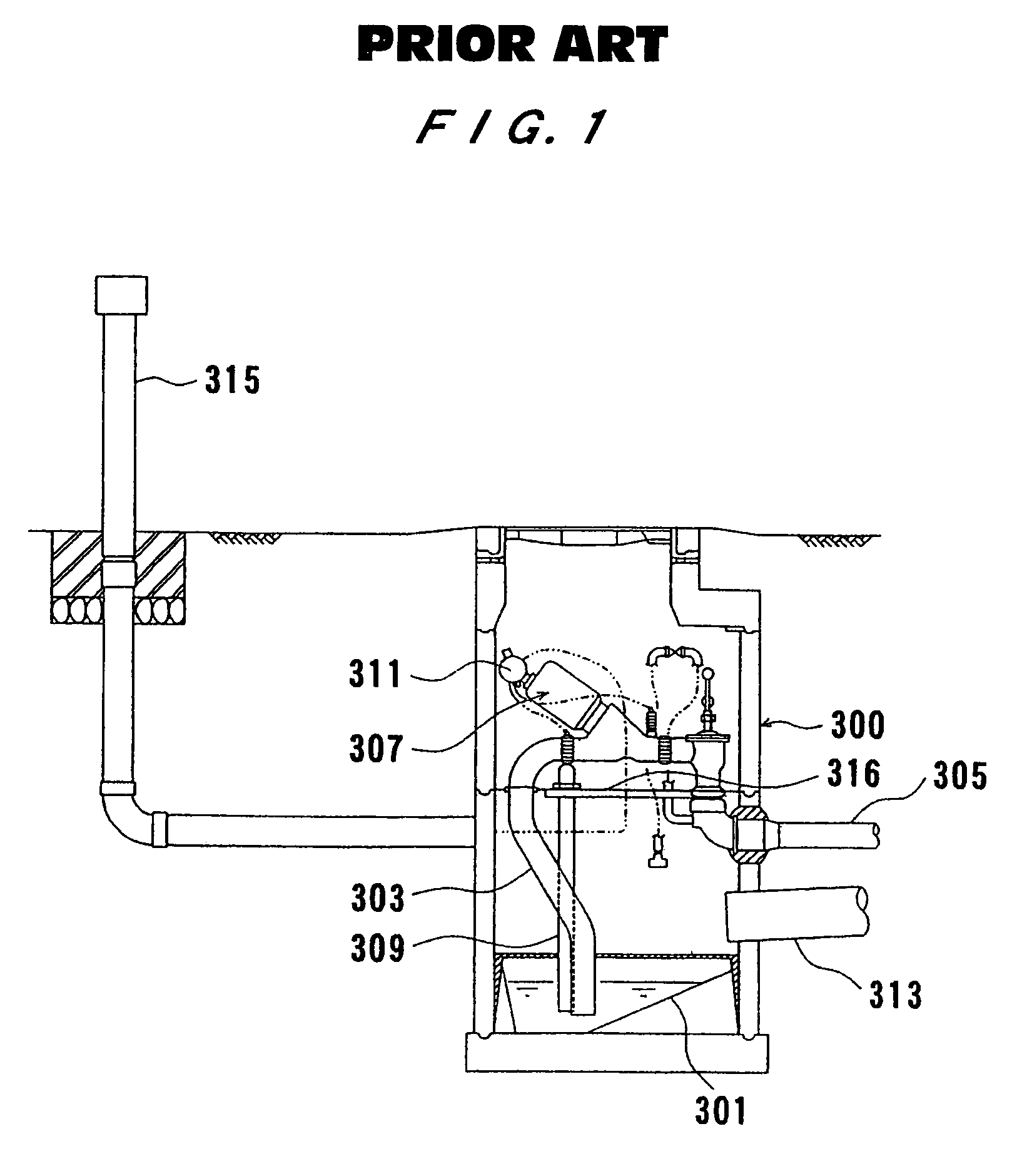
BACKGROUND OF THE INVENTION[0001]1. Field of the Invention[0002]The present invention relates to a vacuum valve controller for opening and closing a vacuum valve mounted on an end of a pipe of a vacuum system that is part of a vacuum sewage system.[0003]2. Description of the Related Art[0004]Heretofore, there has been known a vacuum sewage system which includes a vacuum system having a pipe connected to a sewage pit and delivers sewage stored in the sewage pit to a predetermined site such as a sewage treatment plant under a vacuum pressure developed in the pipe of the vacuum system. The vacuum sewage system has a sewage suction pipe placed in the sewage pit, a vacuum valve for selectively connecting the sewage suction pipe to and disconnecting the sewage suction pipe from the pipe of the vacuum system, and a vacuum valve controller for opening and closing the vacuum valve depending on the water level of sewage in the sewage pit.[0005]FIG. 1 of the accompanying drawings is a sectiona...

Claims


Application Information

Patent Timeline
Patent Type & Authority Patents(United States)
IPC IPC(8): B67C3/16E03F7/00E03F1/00E03F5/22
CPCE03F1/006Y10S137/907E03F1/007Y10T137/3109
Inventor SHIMIZU, OSAMUKAMATA, ISAMU
Owner EBARA CORP
Learn More