Pneumatically operated screw driver

a screw driver and pneumatic technology, applied in the direction of screwdrivers, power driven tools, wrenches, etc., can solve the problems of excessive frictional wear of components, heat generation of components, and rotational components, and achieve high operability and high speed

Inactive Publication Date: 2006-03-21
KOKI HLDG CO LTD
View PDF10 Cites 22 Cited by
  • Summary
  • Abstract
  • Description
  • Claims
  • Application Information

AI Technical Summary

Benefits of technology

[0006]It is therefore an object of the present invention to provide a compact and light-weight pneumatically operated screw driver providing high speed screw fastening with high operability.
[0007]Another object of the present invention is to provide such screw driver avoiding fuse-bonding and any generation of scratch at sliding surfaces of mutually sliding components due to frictionally wearing particles released from the components.
[0008]Still another object of the present invention is to provide such screw driver ensuring stop of a supply of compressed air to the pneumatic motor at the terminal phase of the screw driving operation.
[0009]Still another object of the present invention is to provide such screw driver capable of avoiding excessive rotation of the rotary member at a terminal phase of the screw driving operation in order to avoid excessive screwing operation.

Problems solved by technology

To this effect, new problems arise as to excessive frictional wear of components, particularly rotational components and heat generation of these components due to the excessive friction.

Method used


Image

  • Pneumatically operated screw driver
  • Pneumatically operated screw driver
  • Pneumatically operated screw driver

Examples


Embodiment Construction

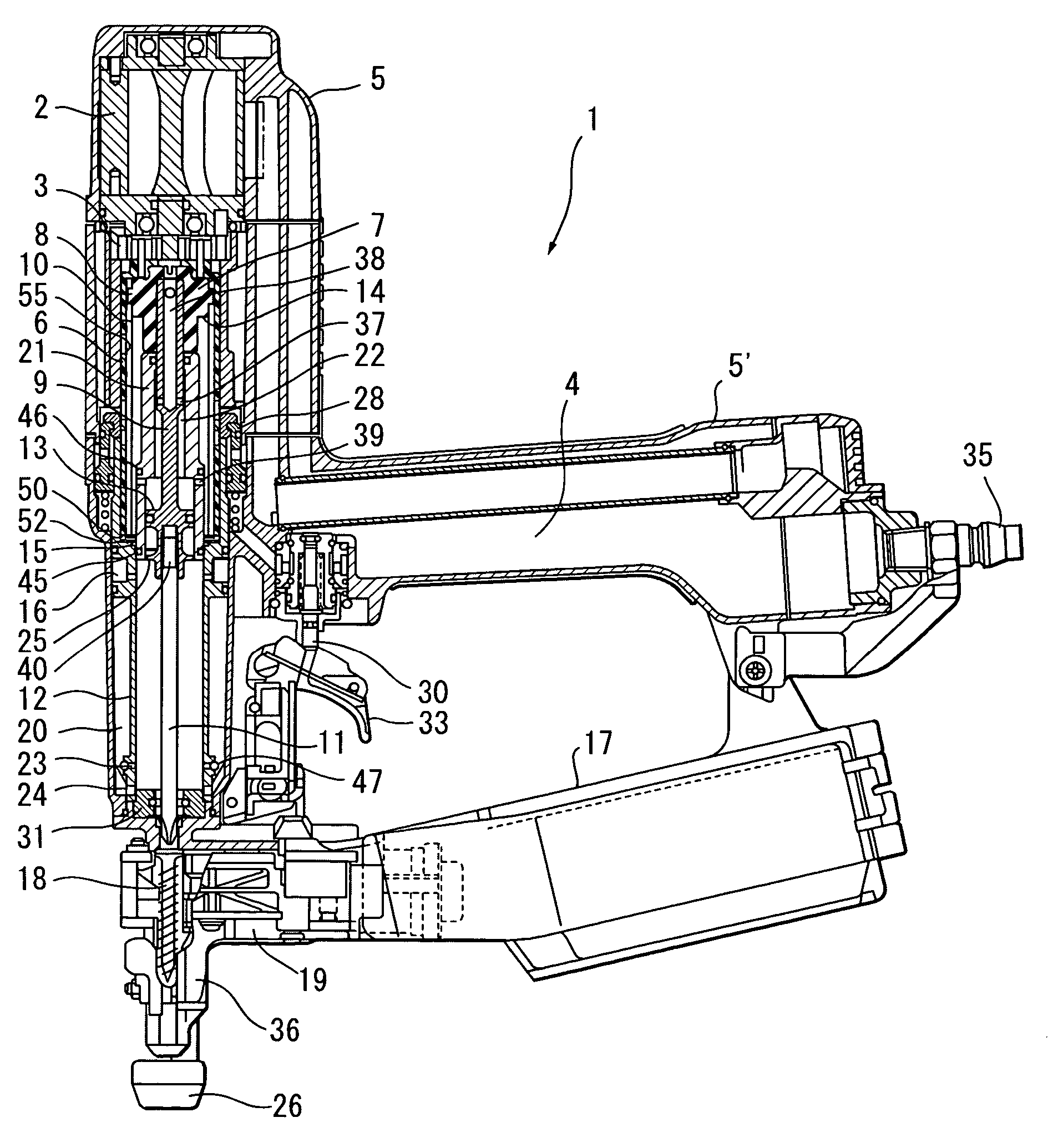
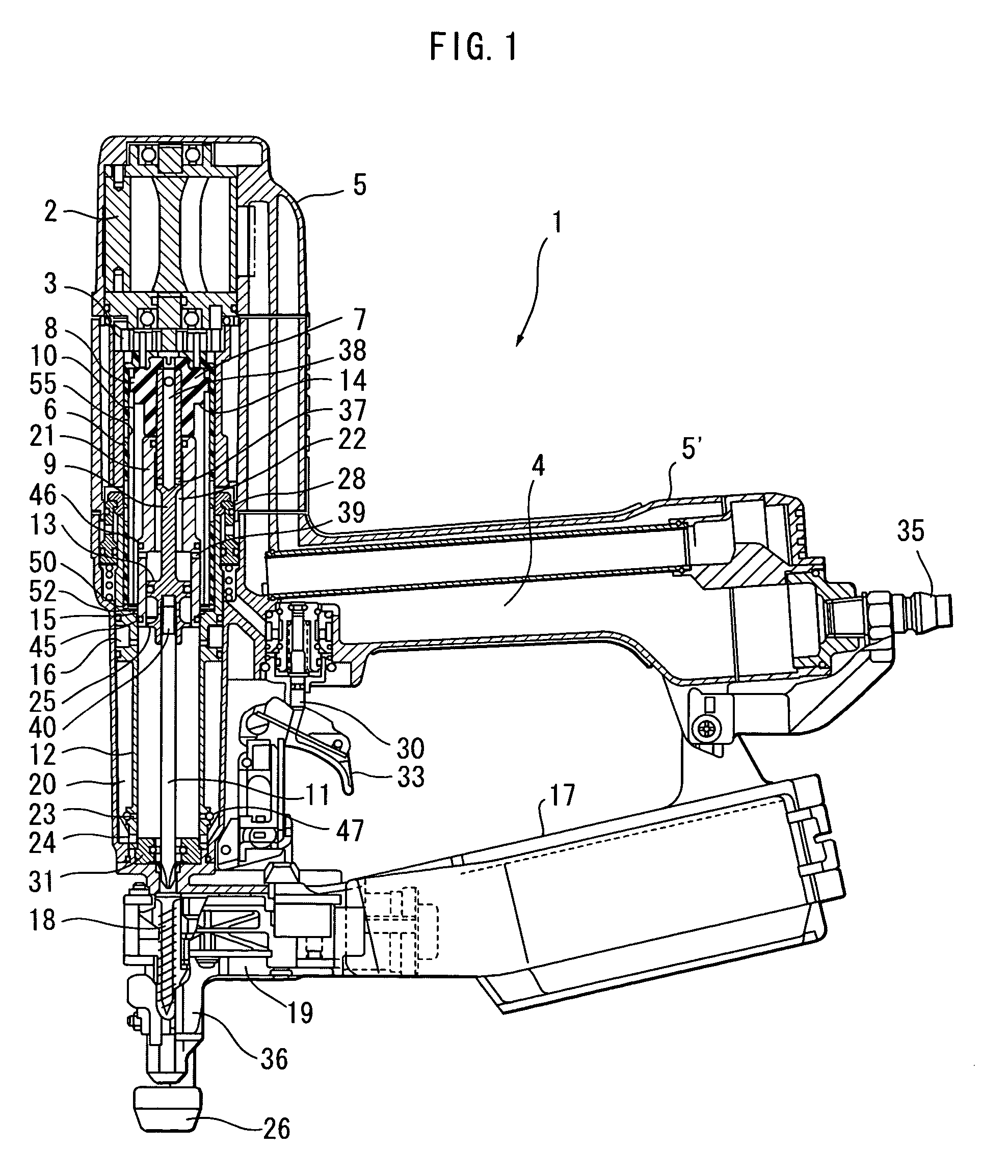
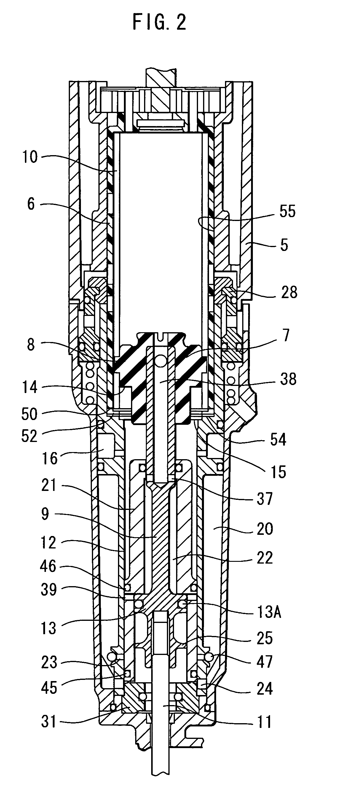
[0020]A pneumatically operated screw driver according to a first embodiment of the present invention will be described with reference to FIGS. 1 through 6. The directions used in the following description are defined based on a screw driver held in a vertical position with a driver bit extending downward and a grip extending rearward. Needless to say, the actual direction of the screw driver will be frequently changed due to its handiness when it is used.

[0021]A pneumatically operated screw driver 1 includes a body 5. The body 5 constitutes an outer frame of a main body. The body 5 includes a handle 5′. The body 5 has an inside space defining a compressed air chamber 4 extending from the handle 5′ to an upper part of the body 5. The body 5 is made from a metal such as a magnesium, an aluminum, and alloy thereof, and the body 5 has an inner peripheral surface 55. The compressed air chamber 4 is in communication with an intake port 35 at the rear end of the handle 5′ for introducing t...


PUM


Abstract

A compact and light-weight pneumatically operated screw driver providing high speed screw fastening with high operability. A rotary member rotationally driven by a pneumatic motor includes a main rotary member made from a plastic material and a sliding segment fixed to the main rotary member. A rotation slide member is axially slidably movable relative to the rotary member and is rotatable together with the rotation of the rotary member. A shut-off section is provided on which the rotation slide member is rotationally seated when the rotation slide member is moved toward the shut-off section. The rotation slide member is made from an elastic material. A sleeve like piston having a seal ring in sliding contact with a cylinder is provided. The seal ring shuts off a supply of compressed air to the pneumatic motor only by the seating of the rotation slide member onto the shut-off section.

Description

CROSS-REFERENCE TO THE RELATED APPLICATION[0001]The present application is closely related to the commonly assigned co-pending U.S. Patent applications titled “pneumatically operated screw driver” filed Sep. 3, 2004 (priority date: Sep. 19, 2003, Ser. No. 10 / 933,326 1297.44201X00), and to another commonly assigned co-pending U.S. patent application titled “pneumatically operated screw driver” (priority date Oct. 1, 2003, Base: JP2003-343293 and JP2003-343295)BACKGROUND OF THE INVENTION[0002]The present invention relates to a pneumatically operated screw driver providing an axially driving force by a piston and rotational force by a pneumatic motor for screwing a threaded fastener into a woody member or the like.[0003]U.S. Pat. No. 6,026,713 discloses a pneumatically operated screw driver including a driver bit engageable with a groove formed in a head of the fastener. The driver bit is connected to a piston which is driven in an axial direction of the driver bit upon application of ...

Claims


Application Information

Patent Timeline
Patent Type & Authority Patents(United States)
IPC IPC(8): B25B21/00B25B21/02
CPCB25B21/023
Inventor SASAKI, YASUOKAMO, TAKESHIWAKABAYASHI, MICHIOOOUCHI, HARUHIKO
Owner KOKI HLDG CO LTD
Why Eureka
Try Eureka