Bare fiber optical connecting devices

a fiber optic connection and fiber technology, applied in the field of fiber optic connectors, can solve the problems of difficult and time-consuming, difficult to provide a perfect cleave, and inconvenient use, and achieve the effects of perfect cleaving of the fiber, and improving the quality of the optic link

Active Publication Date: 2006-03-21
NUVISIONS INT
View PDF3 Cites 7 Cited by
  • Summary
  • Abstract
  • Description
  • Claims
  • Application Information

AI Technical Summary

Benefits of technology

[0009]It is an additional object and advantage of the present invention to provide a fiber optic connector that avoid the need for a perfect cleave in order to work effectively.
[0010]It is a further object and advantage of the present invention to provide a connector that improves the quality of an optic link.
[0011]Other objects and advantages of the present invention will in part be obvious, and in part appear hereinafter.
[0012]In accordance with the foregoing object and advantages, the present invention comprises a quick connect fiber optic connector assembly including a ferrule having a reservoir for holding optical coupling compound, such as a transmitting gel or oil. A cleaved optical fiber is concentrically held within the ferrule for alignment with a receiver. The gel or oil in the reservoir alleviates the need for a perfect cleave of the fiber and improves the quality of the optic link. By releasing a pressure foot of the connector assembly, the fiber may be rotated to minimize transmission losses. The pressure foot consists of special material that is sandwiched around the bare fiber to provide a definite holding mechanism for the bare fiber. Once the transmission signal is optimized, the fiber can tested or used for or communications.
[0013]In another embodiment, the present invention comprises a connector including an enclosed cartridge housing the optical coupling compound. As a bare cable is inserted into the connector it passes through the cartridge and picks up a small quantity of coupling compound before engaging a ferrule. The ferrule includes a small divot for accepting the fiber and compound thereon, and optically interconnects the bare fiber to a patch cable or equipment lead positioned in the opposing side of the ferrule. The cartridge isolates the coupling compound from the environment and provides an easy and mess-free method of applying the oil or gel to the cable interface.

Problems solved by technology

It is difficult and time consuming, however, to provide a perfect cleave.
These systems are very expensive, bulky, and are not user-friendly when employed in the field.
In addition to requiring a manual application of the oil or gel, conventional systems are also disadvantageous because the oil or gel is exposed to the contaminants in the environment, such as dust and debris.

Method used


Image

  • Bare fiber optical connecting devices
  • Bare fiber optical connecting devices
  • Bare fiber optical connecting devices

Examples


Embodiment Construction

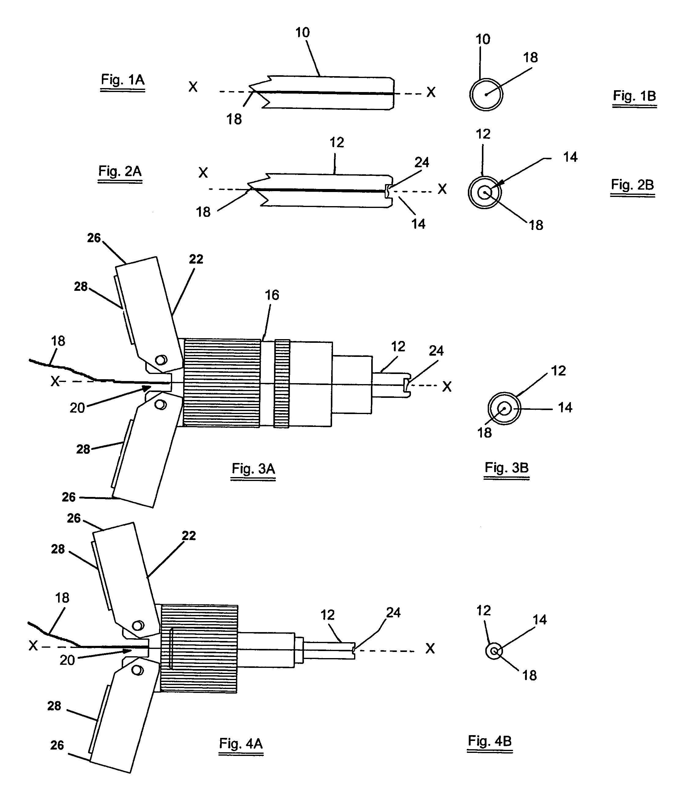
[0022]Referring to the drawings wherein like numerals refer to like parts throughout, there is seen in FIGS. 1A and 1B a conventional fiber optic ferrule 10 used in connectors and adapters for accepting bare fibers.

[0023]As seen in FIGS. 2A and 2B, a ferrule 12 extending along a longitudinal axis X—X includes a recess or cavity formed at one end of the ferrule that defines a reservoir 14. Reservoir 14 is concentrically positioned about axis X—X and adapted to retain an optical gel or oil 24 therein that aids in the transmission of the light through connector. The gel or oil is a conventional optical coupling compound for normal operating conditions.

[0024]As seen in FIGS. 3A and 3B, ferrule 12 including reservoir 14 can be provided in a conventional bare fiber adapter 16. In order to make a quick connection, a bare fiber 18 is cleaved and inserted into the receiving end of adapter 16 through a bore 20 formed along longitudinal axis X—X until it reaches end of bore 20 and terminates a...


PUM


Abstract

A quick connect fiber optic connector assembly for testing and communication that uses a modified ferrule having a reservoir formed into its tip for holding optic transmitting gel or oil. A cleaved optical fiber may be held concentrically within the ferrule for alignment with a receiver or optical device. The gel or oil in the reservoir alleviates the need for a perfect cleave of the fiber and allows for transmission of the optic signal. If necessary, the pressure foot of the connector assembly may be rotated to minimize transmission losses. When the transmission signal is optimized, the fiber may be tested or used for communications. In another embodiment of the invention, a connector assembly includes a removable cartridge housing optical coupling compound. As a bare fiber is passed into the connector it picks up a small quantity of coupling compound and is then interconnected to an optical patch cable.

Description

CROSS-REFERENCE TO RELATED APPLICATION[0001]The present application claims priority to U.S. Provisional Application Ser. No. 60 / 466,022, filed Apr. 25, 2003 and entitled Ferrule Reservoir for Bare Fiber Optic Cables, hereby incorporated by reference.BACKGROUND OF THE INVENTION[0002]1. Field of Invention[0003]The present invention relates to fiber optic connectors and, more specifically, to ferrules for connecting bare fiber optic interfaces to test, measurement, and connection equipment.[0004]2. Description of Prior Art[0005]The fiber optic industry often requires a connection to bare fibers in order to test transmission capabilities or establish communications. Currently, a special tool called a cleaver is used to provide a clean break on the end of a bare fiber so that it may be connected to a specially designed bare fiber adapter. It is difficult and time consuming, however, to provide a perfect cleave. As a result, there are devices that can quickly connect to the bare end of th...

Claims


Application Information

Patent Timeline
Patent Type & Authority Patents(United States)
IPC IPC(8): G02B6/36G02B6/38
CPCG02B6/382
Inventor CHUDOBA, PAUL S.
Owner NUVISIONS INT
Why Eureka
Try Eureka