Retaining socket for electrical outlets

a technology for retaining sockets and electrical outlets, applied in the direction of coupling device connections, coupling parts engagement/disengagement, incorrect coupling prevention, etc., can solve the problems of insufficient protection against tension from all directions, numerous additional components attached, and presenting obstacles, etc., to achieve the effect of being cheap to manufactur

Inactive Publication Date: 2006-03-21
BATTARD DEREK J
View PDF13 Cites 64 Cited by
  • Summary
  • Abstract
  • Description
  • Claims
  • Application Information

AI Technical Summary

Benefits of technology

[0017]It is yet another object to provide a retaining system which is inexpen

Problems solved by technology

Various devices have attempted to address this issue, but each have their own disadvantages.
For example, some do not satisfactory protect against tensions from all directions relative to the outlet.
Others are permanently at

Method used


Image

  • Retaining socket for electrical outlets
  • Retaining socket for electrical outlets
  • Retaining socket for electrical outlets

Examples


Embodiment Construction

[0030]Detailed descriptions of one or more preferred embodiments are provided herein. It is to be understood, however, that the present invention may be embodied in various forms. Therefore, specific details disclosed herein are not to be interpreted as limiting, but rather as a basis for the claims and as a representative basis for teaching one skilled in the art to employ the present invention in any appropriate system, structure or manner.

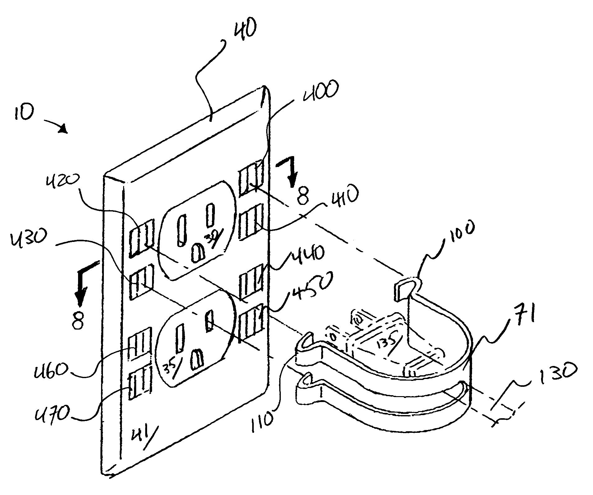
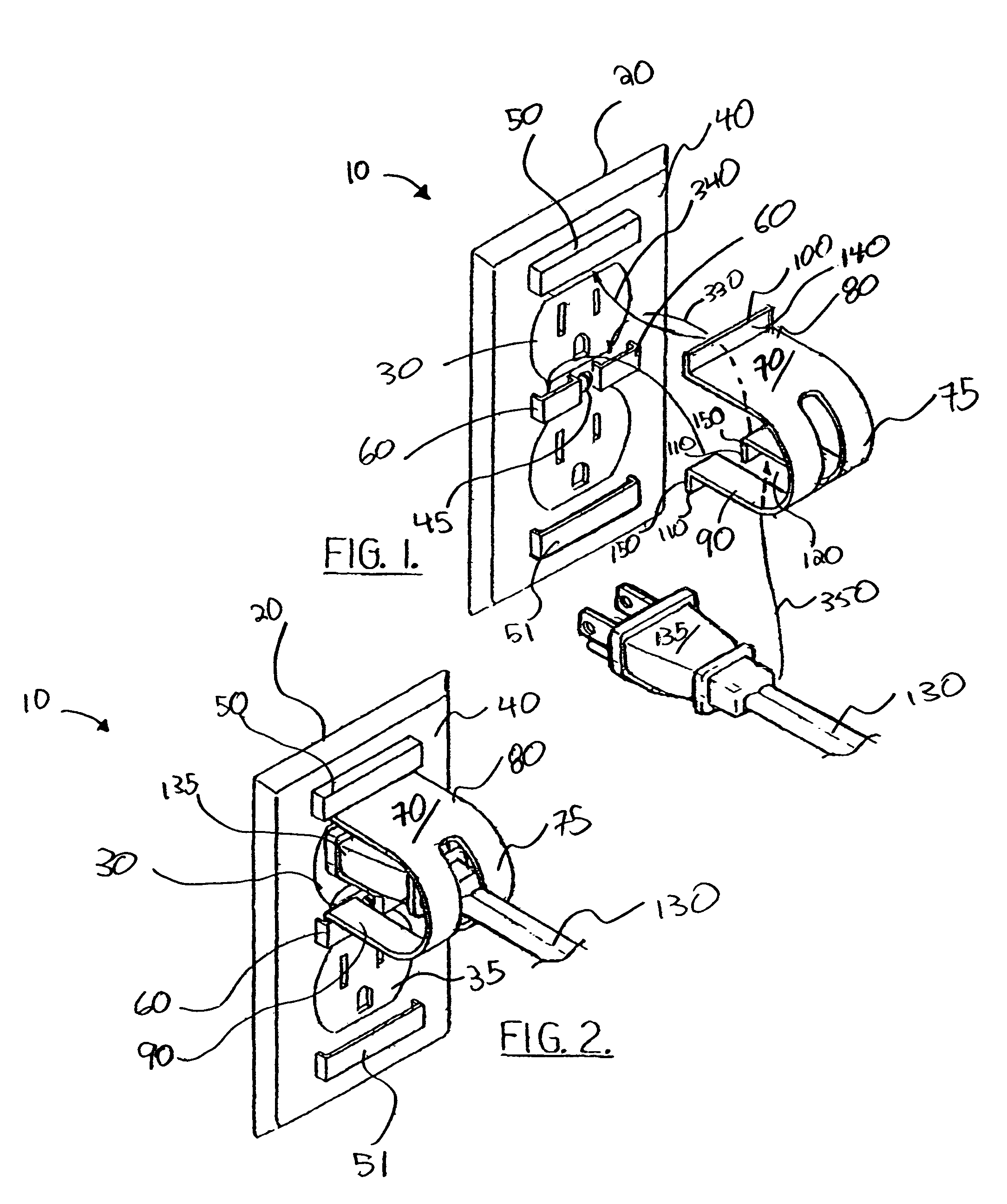
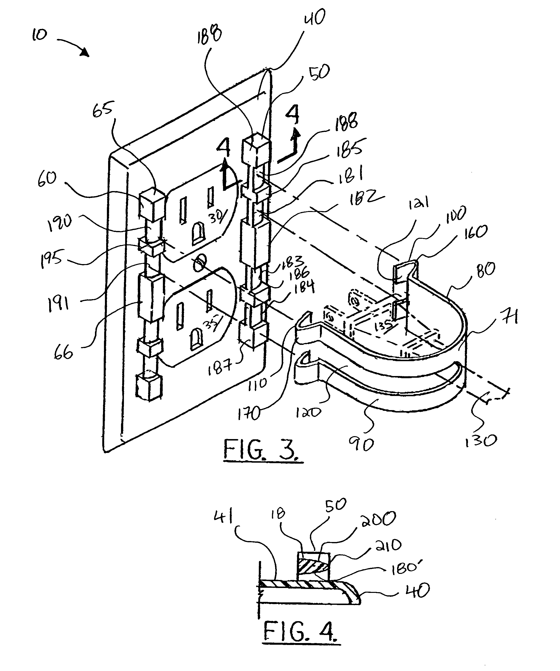
[0031]Electrical plug retainer is generally indicated reference numeral 10 in the drawings and is adapted to retain plug 135, carried by cord 130, in a conventional wall receptacle 20. Electrical plug retainer 10, as illustrated in FIGS. 1–6, generally includes a modified receptacle plate (generally indicated by reference numeral 40) and clip (generally indicated by reference numeral 70) having a slot 120 which slot allows passage of cord 130, but not plug 135. When attached to face plate 40, clip 70 retains plug 135 in socket 30. Clip 70 retain...


PUM


Abstract

A retaining clip for retaining a plug carried by a cord in a socket of an electrical receptacle which includes, in one embodiment, a plate mountable to the receptacle, a clip mountable on the plate and resisting efforts to pull out an electrical plug plugged into the socket.

Description

CROSS-REFERENCE TO RELATED APPLICATIONS[0001]This is a continuation-in-part of U.S. patent application Ser. No. 10 / 617,282, filed Jul. 10, 2003 now abandoned.[0002]U.S. patent application Ser. No. 10 / 617,282, filed Jul. 10, 2003, is incorporated herein by reference.[0003]Priority is claimed to U.S. patent application Ser. No. 10 / 617,282, filed Jul. 10, 2003.STATEMENT REGARDING FEDERALLY SPONSORED RESEARCH OR DEVELOPMENT[0004]Not applicableREFERENCE TO A “MICROFICHE APPENDIX”[0005]Not applicableBACKGROUND[0006]1. Field[0007]The present invention relates to a retaining socket for an electrical outlet. More particularly, the present invention relates to a retaining socket which can resist the pulling out of an electrical plug regardless of which direction tension is placed on an electrical cord.[0008]2. General Background[0009]A plug for an electrical appliance, such as a vacuum cleaner, can become loosened or pulled from its outlet when the appliance is attempted to be moved to a work...

Claims


Application Information

Patent Timeline
IPC IPC(8): H01R13/64
CPCH01R13/6395
Inventor BATTARD, DEREK J.
Owner BATTARD DEREK J
Why Eureka
Try Eureka