Battery control apparatus

a battery control and battery technology, applied in battery/fuel cell control arrangement, secondary cell servicing/maintenance, hybrid vehicles, etc., can solve the problems of increased manufacturing cost of vehicles and complicated vehicle structure, and achieve the effect of increasing the temperature of batteries and preventing the reduction of available input-output power of batteries

Inactive Publication Date: 2006-03-21
MITSUBISHI MOTORS CORP
View PDF7 Cites 41 Cited by
  • Summary
  • Abstract
  • Description
  • Claims
  • Application Information

AI Technical Summary

Benefits of technology

[0009]It is therefore an object of the present invention to provide a battery control apparatus that is capable of increasing the temperature of a battery in an efficient manner to prevent the available input-output power of the battery from being reduced due to a decrease in battery temperature.

Problems solved by technology

However, this necessitates adding parts such as the heater and thus causes such problems that the cost for manufacturing the vehicle is increased and the structure of the vehicle is complicated.

Method used


Image

  • Battery control apparatus
  • Battery control apparatus
  • Battery control apparatus

Examples


Embodiment Construction

[0019]A description will now be given of a battery control apparatus provided in a series type hybrid vehicle according to an embodiment of the present invention with reference to the accompanying drawings.

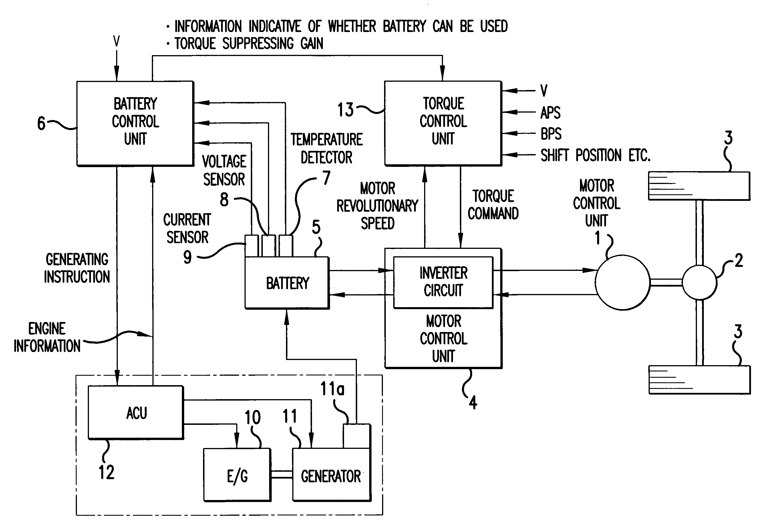
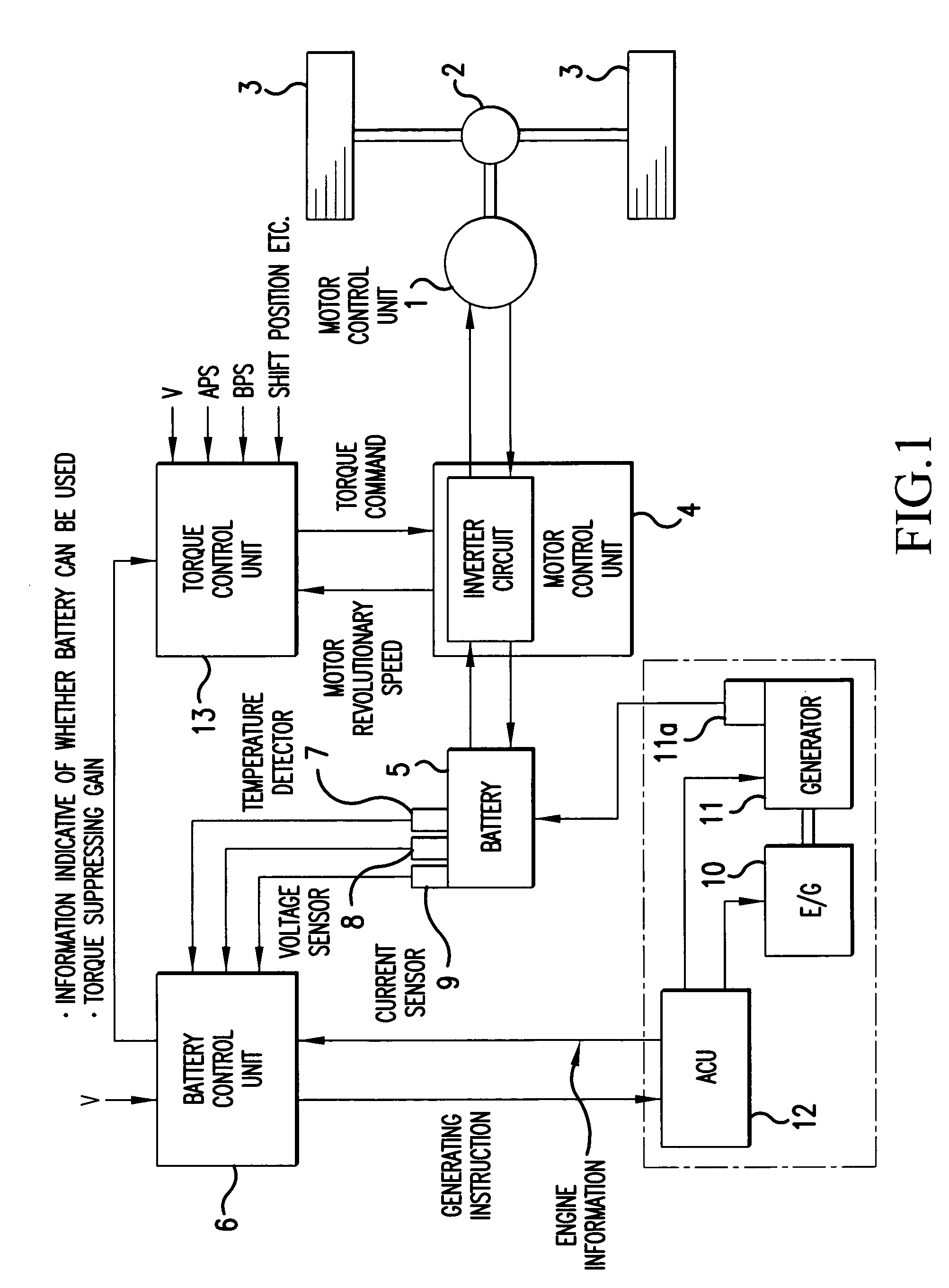
[0020]FIG. 1 is a block diagram showing the entire construction of the battery control apparatus according to the present embodiment. As shown in FIG. 1, a vehicle is equipped with a motor / generator 1 that produces power for driving the vehicle, and the motor / generator 1 is connected to right and left driving wheels 3 via a differential gear 2. The motor / generator 1 is connected to a driving battery 5 via an inverter circuit incorporated in an MCU (Motor Control Unit) 4, which is connected to a BCU (Battery Control Unit) 6 via a TCU (Torque Control Unit) 13. The BCU 6 causes the TCU 13 to calculate motor torque, and the MCU 4 is driven in accordance with an instruction given from the TCU 13. With this arrangement, the supply of power from the battery 5 to the motor / generator 1, an...


PUM

PropertyMeasurementUnit
temperatureaaaaaaaaaa
thresholdaaaaaaaaaa
temperatureaaaaaaaaaa

Abstract

There is provided a battery control apparatus that, when the battery temperature is low, repeats the charge and discharge of a battery on a short cycle such that the state of charge (SOC) of the battery lies in the range of 30 to 40% if the present SOC is less than 50%, and repeats the charge and discharge of the battery on a short cycle such that the SOC lies in the range of 50 to 60% if the present SOC is equal to or greater than 50%, thus increasing the temperature of the battery. Therefore, it is possible to increase the battery temperature in an efficient manner, and to prevent the available input-output power of the battery from being reduced due to a decrease in the battery temperature.

Description

CROSS-REFERENCE TO THE RELATED APPLICATION[0001]This non-provisional application incorporates by reference the subject matter of Application No. 2002-074601, filed in Japan on Mar. 18, 2002, on which a priority claim is based under 35 U.S.C. §119(a).BACKGROUND OF THE INVENTION[0002](1) Field of the Invention[0003]The present invention relates to a battery control apparatus that controls the charge and discharge of a battery.[0004](2) Description of the Related Art[0005]For example, in a series type hybrid vehicle equipped with a generator for driving an engine and a motor for driving the vehicle, the power generation of the generator is controlled such that the state of charge (SOC) indicating the remaining capacity of a battery is maintained in a predetermined range.[0006]In this type of vehicle, since power from the battery drives the motor, the driving performance of the vehicle depends largely on the available input-output power of the battery. There are a variety of factors tha...

Claims


Application Information

Patent Timeline
Patent Type & Authority Patents(United States)
IPC IPC(8): H02J7/16B60W20/00B60K6/445B60L11/18B60L50/16B60W10/26H01M10/44H02J7/00
CPCB60K6/445B60L11/1851B60W10/26H02J7/0077H02J7/0091B60W20/106Y02T10/6239Y02T10/705B60W2510/244B60W2510/246Y02T10/7005B60W20/13B60L7/14B60L15/2009B60L2210/30B60L2210/40B60L2240/12B60L2240/421B60L2240/423B60L2240/441B60L2240/443B60L2240/545B60L2240/547B60L2240/549B60L50/61B60L50/16B60L58/13B60L58/25H02J7/00712Y02T10/62Y02T10/64Y02T10/70Y02T10/7072Y02T10/72H02J7/007194
Inventor KOHAMA, HIROFUMIYOSHIDA, HIROAKIFURUKAWA, NOBUYA
Owner MITSUBISHI MOTORS CORP
Why Eureka
Try Eureka