Apparatus, device and method for generating magnetic field gradient

a magnetic field gradient and gradient technology, applied in the field of magnetic fields, can solve the problems of loss of most of the magnetization, no known effective method for manufacturing a magnet device with corresponding dimensional precision, and inability to avoid the debris of magnetic particles, and achieve high magnetic field gradient

Inactive Publication Date: 2006-03-21
JDS UNIPHASE CORP
View PDF13 Cites 30 Cited by
  • Summary
  • Abstract
  • Description
  • Claims
  • Application Information

AI Technical Summary

Benefits of technology

[0017]A magnet device, apparatus and method is needed with dimensional precision that can produce a high magnetic field gradient at one or more locations, while avoiding the magnetic particle debris of other devic

Problems solved by technology

Conversely, they lose most of their magnetization when an applied field is removed.
While these methods of using magnet arrays assembled from many small magnets produce a high magnetic field gradient, there are several disadvantages that pose significant design and performance challenges.
The mechanical tolerances of each part accumulate so that the position of any one part is poorly determined.
For instance, though it is possible to micro-machine a silicon chip consisting of an array of actuators with extreme dimensional precision, there is no known effective method for manufacturing a magnet device with corresponding dimensional precision to provide a large number of regions with high magnetic field gradient.
Hence, the magnets may end up in the wrong position (i.e. not centered with actuator or not in ideal position) due to tolerance build up.
These types of dimensional errors in a magnet array are signifi

Method used


Image

  • Apparatus, device and method for generating magnetic field gradient
  • Apparatus, device and method for generating magnetic field gradient
  • Apparatus, device and method for generating magnetic field gradient

Examples


Embodiment Construction

[0063]Reference will now be made in detail to the present preferred embodiments of the invention, examples of which are illustrated in the accompanying drawings. Wherever possible, the same reference numbers will be used throughout the drawings to refer to the same or like parts.

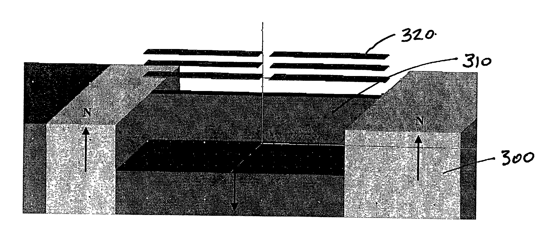
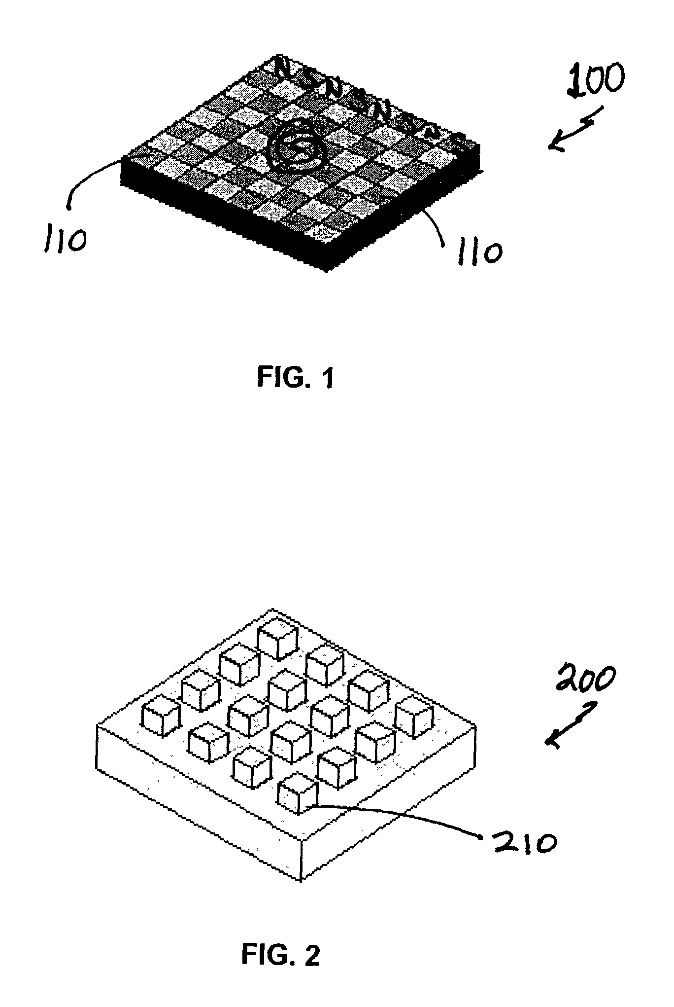
[0064]Referring now to FIG. 1, a non-monolithic structure including individual magnets 110 assembled into a magnet array 100 is shown. The different shades in the arrangement represent different magnetic polarity, either north (pointing up out of the plane of the array) or south (pointing down out of the plane of the array). Hence, this structure may be referred to as the “checkerboard” structure. Due to alternating N / S polarity of the checkerboard magnets, the field above the magnets has a rapid spatial variation. This high field gradient is useful in actuating certain classes of electromagnetic actuators.

[0065]The force F on a magnetic dipole (m) in a field gradient is given by the equation:

F=∇({overscore ...


PUM


Abstract

A monolithic or dual monolithic magnetic device or apparatus having an array of formations such as protruding or raised nubs wherein adjacent nubs have the same or opposite polarity to produce a high magnetic field gradient in the vicinity of the nubs is described. In lieu of nubs, the use of a magnetic device with thru-holes, blind holes, filled holes, or iron flux concentrators is also detailed, wherein all embodiments result in regions of high magnetic field gradient. Apparatus and methods for spot-poling a magnet array are also illustrated.
An application of an array of MEMS actuators using the magnets of the present invention to produce high field gradient at precise locations is described. A further application of a biochemical separation unit containing a magnetic array and micro-fluidic channels for separating out magnetic particles tagged with bio-specific molecules for sensing the presence of a disease or specified chemicals is also described.

Description

FIELD OF THE INVENTION[0001]This invention relates generally to magnetic fields, and more particularly for generating and using electromagnetic field gradients in applications such as actuation of MEMS arrays.BACKGROUND OF THE INVENTION[0002]As it is known in the art, magnetic forces can be used to induce mechanical motion or actuation of magnetic materials.[0003]Electric current flowing through a conductor (e.g. a wire) induces a magnetic field around the conductor due to Faraday's law of induction (e.g. an electromagnet). The actuation of the electromagnet creates a magnetic field and hence regions of field gradient.[0004]Such actuation has many applications. For instance, many electromechanical switch designs rely upon a magnetic field or field gradient, where a mechanical electrode is pulled into contact with another electrode via magnetic force. For instance, magnetic switching mechanisms have been used to actuate Micro-Electro-Mechanical (MEMS) switches. Typically, in these el...

Claims


Application Information

Patent Timeline
IPC IPC(8): H01F7/20G02B26/08
CPCG02B26/0841
Inventor BERNSTEIN, JONATHAN JAYTAYLOR, WILLIAM PATRICKBRAZZLE, JOHN DAVIDCORCORAN, CHRISTOPHER JOHNLEE, JAMES KELLY
Owner JDS UNIPHASE CORP
Why Eureka
Try Eureka