Pulse width modulation based digital incremental encoder

a digital incremental encoder and pulse width modulation technology, applied in the field of position measurement, can solve the problem of limited number of tracks per revolution

Active Publication Date: 2006-03-21
BEI SENSORS & SYST
View PDF2 Cites 4 Cited by
  • Summary
  • Abstract
  • Description
  • Claims
  • Application Information

AI Technical Summary

Problems solved by technology

However, the number of tracks per revolution is limited by physical line spacing and quality of light transmission.

Method used


Image

  • Pulse width modulation based digital incremental encoder
  • Pulse width modulation based digital incremental encoder
  • Pulse width modulation based digital incremental encoder

Examples


Embodiment Construction

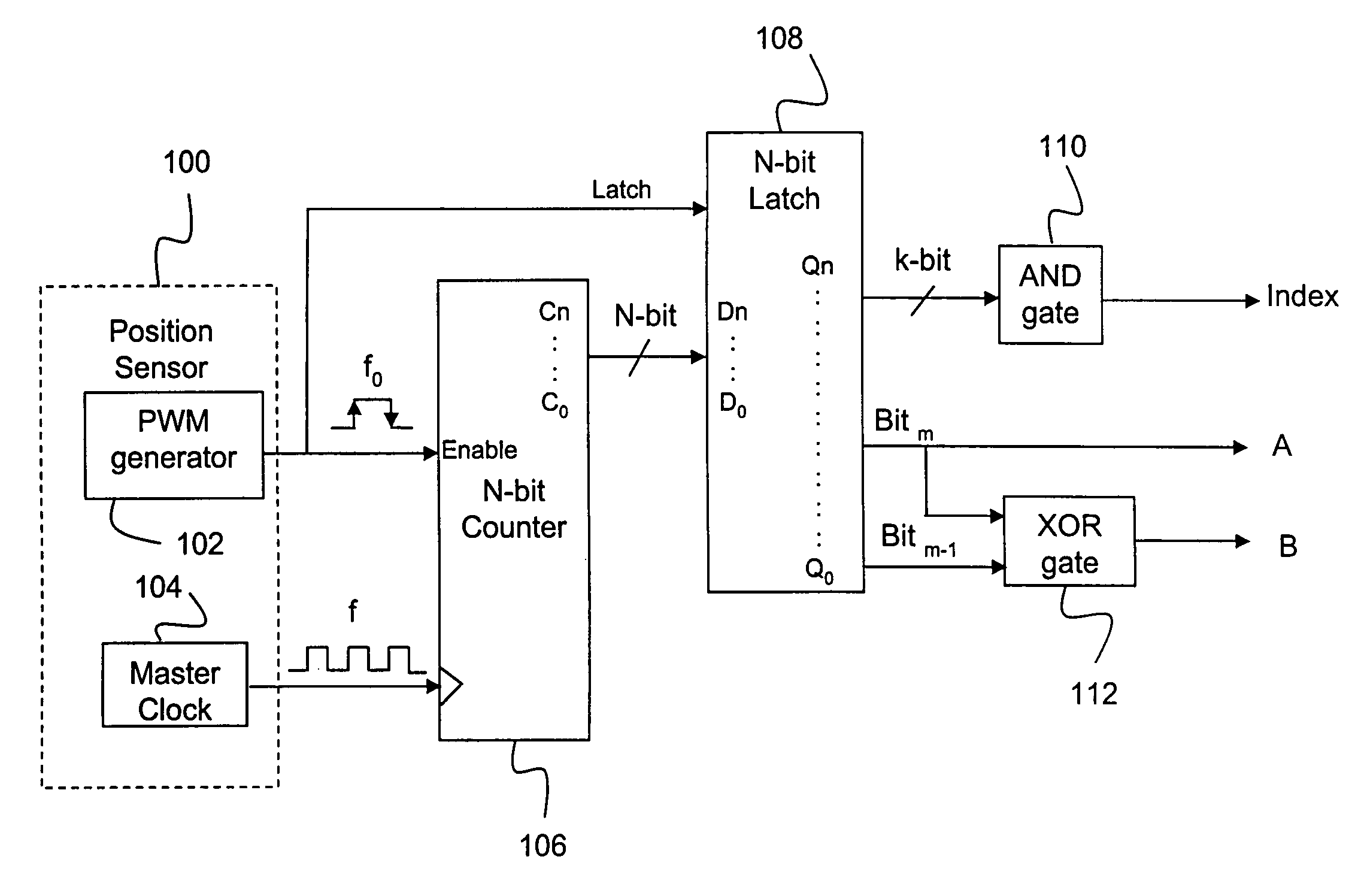
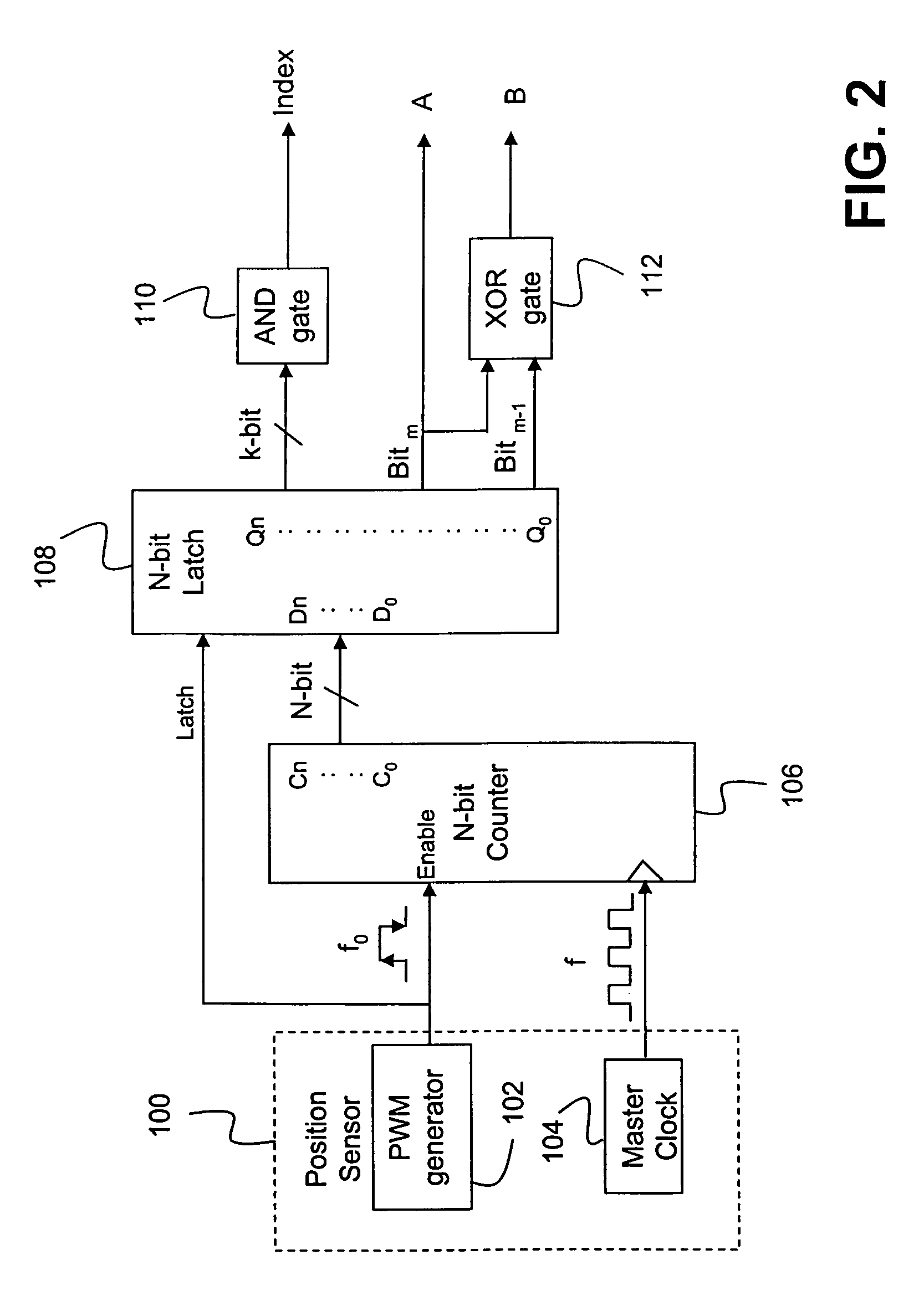
[0017]In exemplary embodiments of the present invention, instead of using the above referenced optical encoding technique, a PWM signal generated using an angular position sensor is used for incremental encoding. The PWM signal includes angular position information of a rotating disk on a shaft in PWM format with analog resolution. A PWM based digital incremental encoder receives the PWM signal, and uses it to derive information on the speed and direction of rotation.

[0018]The PWM signal and a high speed clock signal are applied to a counter in the digital incremental encoder to generate a multi-bit output which varies in accordance with the duty cycle of the PWM signal. For instance, the value of the multi-bit output corresponds to the number of clock cycles counted while the PWM signal is at a high state, and therefore, indicates the angular position of the rotating disk. The counter is also used to decode in digital form the direction and speed of rotation measured by the angular...


PUM


Abstract

A digital incremental encoder for generating an output signal indicative of an angular position, a direction of rotation, and a speed of rotation of a shaft. A counter receives a PWM signal indicative of the angular position of the shaft and a clock signal from an angular position sensor, and generates a multi-bit output. A latch latches the multi-bit output, a first bit and a second bit of which are used to generate the output signals that include the first bit. The first bit and the second bit may be XOR'd together to generate an XOR output included in the output signals. A direction of rotation may be derived from a quadrature phase relationship between the first bit and the XOR output. The angular position sensor may be an NCAPS or MT-NCAPS. A linear position sensor may be used instead of an angular position sensor to generate the PWM signal.

Description

FIELD OF THE INVENTION[0001]This invention is related to position measurement, and more particularly to a digital incremental encoder for deriving position, speed and direction information from a pulse width modulation (PWM) signal generated by a position sensor.BACKGROUND OF THE INVENTION[0002]For the measurement of angular position, incremental encoders are commonly used. The incremental encoders are mechanical devices that create a number of square waves corresponding to the detected mechanical increments.[0003]Conventional incremental encoders are based on optical technology. An optical incremental encoder includes a patterned encoder disc mounted on a shaft and optical sensors. As the disk rotates via the shaft, the tracks on the disk interrupt the beams between the photo emitter-detector pairs, thereby producing sequences of digital pulses, i.e., square waves. The faster the disc rotates, the higher the frequency of the output square waves. Hence, the frequency of the square w...

Claims


Application Information

Patent Timeline
Patent Type & Authority Patents(United States)
IPC IPC(8): H03M1/10G01D5/244G01D5/20G01D5/245
CPCG01D5/245G01D5/2053
Inventor MADNI, ASAD M.VUONG, JIM B.VUONG, PHILIP
Owner BEI SENSORS & SYST
Why Eureka
Try Eureka