Alignment apparatus, control method therefor, exposure apparatus, device manufacturing method, semiconductor manufacturing factory, and exposure apparatus maintenance method

a technology of alignment apparatus and control method, which is applied in the direction of photomechanical apparatus, instruments, optics, etc., can solve the problems of inability to anticipate the increase in the dynamic characteristics of the stage, the indefinite magnitude of errors, and the increase in the mass of the mirror to be mounted on the stag

Inactive Publication Date: 2006-03-21
CANON KK
View PDF15 Cites 17 Cited by
  • Summary
  • Abstract
  • Description
  • Claims
  • Application Information

AI Technical Summary

Benefits of technology

[0013]The present invention has been made in consideration of the above-mentioned problems, and has as its object t

Problems solved by technology

Consequently, the mass of the mirror to be mounted on the stage increases to decrease the natural frequency, and an increase in dynamic characteristics of the stage cannot be expected.
Variations in periods of time required for the presetting cause an error to have an indefinite magnitude, and the error magnitude of the current position held by each interferometer accumulates.
However, in the above-mentioned remedies, an interferom

Method used


Image

  • Alignment apparatus, control method therefor, exposure apparatus, device manufacturing method, semiconductor manufacturing factory, and exposure apparatus maintenance method
  • Alignment apparatus, control method therefor, exposure apparatus, device manufacturing method, semiconductor manufacturing factory, and exposure apparatus maintenance method
  • Alignment apparatus, control method therefor, exposure apparatus, device manufacturing method, semiconductor manufacturing factory, and exposure apparatus maintenance method

Examples


first embodiment

[First Embodiment]

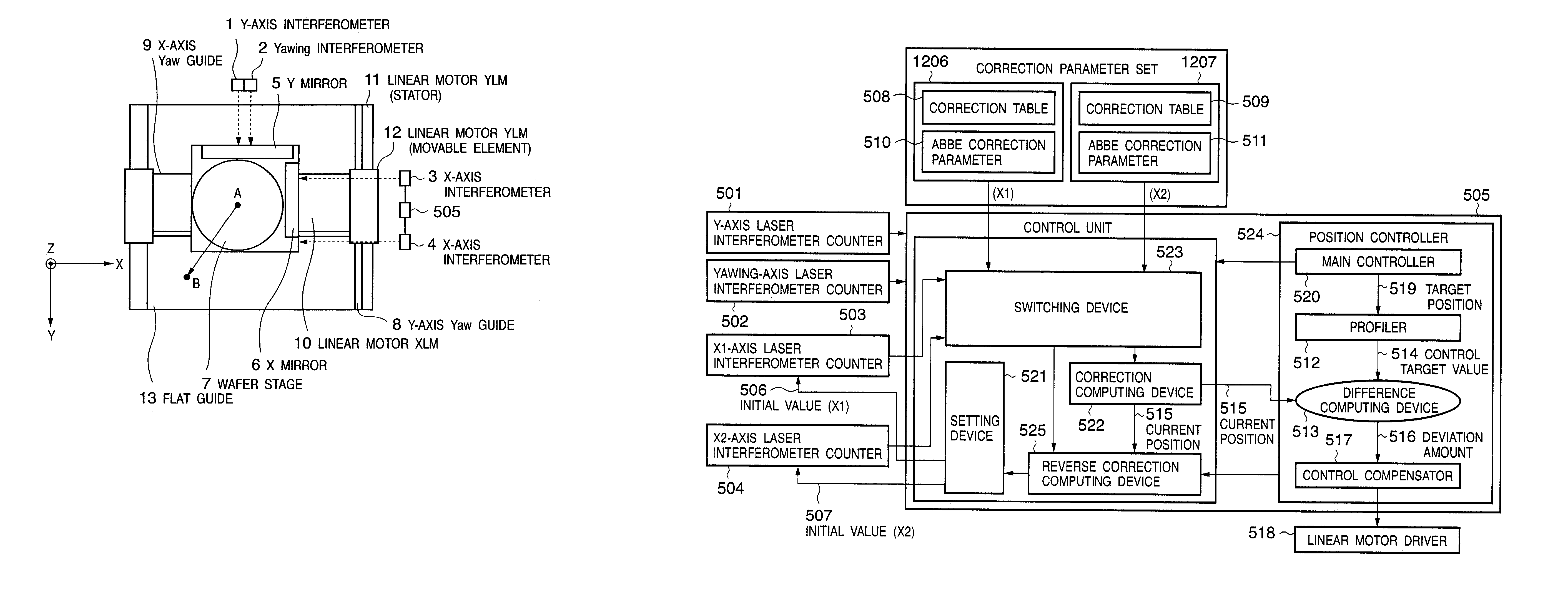
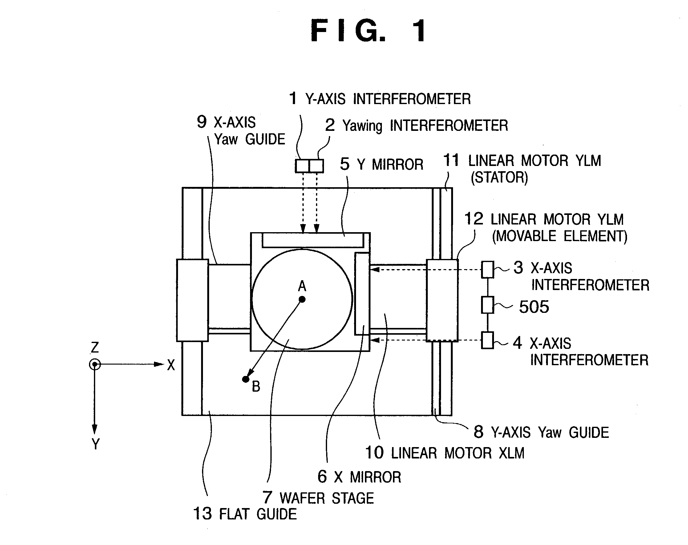
[0058]FIG. 1 is a view showing an example of an alignment apparatus according to a preferred embodiment of the present invention and particularly shows a case wherein the alignment apparatus is applied to the wafer stage of a semiconductor exposure apparatus. A wafer chuck (not shown), an X mirror 6, and a Y mirror 5 are mounted on a wafer stage 7. The X mirror 6 reflects measurement light from an X-axis interferometer 3 or an X-axis interferometer 4 and is used to measure the position coordinate, in the X-axis direction, of the wafer stage 7. The Y mirror 5 reflects measurement light from a Y-axis interferometer 1 and a yawing interferometer 2 and is used to measure the position coordinate, in the Y-axis direction, of the wafer stage 7. A linear motor XLM 10 drives the wafer stage 7 in the X direction and is guided by an X-axis yaw guide 9. A linear motor YLM (stator) 11 drives a linear motor YLM (movable element) 12 in the Y direction and is guided by a Y-axis ya...

second embodiment

[Second Embodiment]

[0089]FIG. 9 is a view showing an example of an alignment apparatus according to another preferred embodiment of the present invention. The same reference numerals denote parts with substantially the same functions as those in the first embodiment. The difference from the first embodiment lies in that a plurality of interferometer axes are arranged with respect to the X-axis in the first embodiment, while a plurality of interferometer axes are arranged with respect to the Z-axis in this embodiment. The Y mirror 5 in FIG. 1 corresponds to a YZ1 mirror 901 in FIG. 9, and the YZ1 mirror 901 is also used as a bar mirror which reflects measurement light of the first Z-axis laser interferometer (not shown) located in the Z-axis direction of FIG. 9. In addition, a Z2 mirror 902 is arranged on the opposite side of the YZ1 mirror 901 to reflect measurement light of the second Z-axis laser interferometer (not shown). Measurement light beams from the Z-axis laser interferome...


PUM


Abstract

An alignment apparatus including a first position measuring device and a second position measuring device which measure position information of an object to be controlled, a switching device which switches a position measuring system from the first position measuring device to the second position measuring device, depending on a moving area of the object to be controlled, a correction computing device which performs a correction calculation for a measurement result from the first position measuring device using a first correction parameter set to obtain a current position of the object to be controlled, a predicted coordinate computing unit which predicts coordinates of the object to be controlled on the basis of progress of a correction calculation result from the correction computing device, and a reverse correction computing device which performs a calculation for the coordinates predicted by the predicted coordinate computing unit using a second correction parameter set to obtain a command value for the second position measuring device.

Description

FIELD OF THE INVENTION[0001]The present invention relates to an alignment apparatus, a control method therefor, an exposure apparatus, a device manufacturing method, a semiconductor manufacturing factory, and an exposure apparatus maintenance method.BACKGROUND OF THE INVENTION[0002]In a stage control system using a laser interferometer, an interferometer which measures the position of a stage generally has one measurement axis per one degree of freedom of a driving shaft, as disclosed in, e.g., Japanese Patent Laid-Open No. 10-289943. However, to increase the driving stroke of the stage in this control system, a reflection mirror which reflects measurement light from the interferometer needs to have a length corresponding to that of the driving stroke. Consequently, the mass of the mirror to be mounted on the stage increases to decrease the natural frequency, and an increase in dynamic characteristics of the stage cannot be expected.[0003]Japanese Patent Laid-Open No. 2001-23891 dis...

Claims


Application Information

Patent Timeline
IPC IPC(8): G01B9/02G01B11/00G03F7/20G03F7/22G03F9/00H01L21/027
CPCG03F7/70775G03F7/70725
Inventor KUROSAWA, HIROSHI
Owner CANON KK
Why Eureka
Try Eureka