Robot hand for transferring an article in a housing, and a library apparatus equipped with the robot hand for transferring and article stored in a rack

Inactive Publication Date: 2006-03-21
FUJITSU LTD
View PDF11 Cites 13 Cited by
  • Summary
  • Abstract
  • Description
  • Claims
  • Application Information

AI Technical Summary

Benefits of technology

[0023]Also, there is achieved a robot hand and a library apparatus comprising the robot hand that is reliable, occupies small mounting space and has simple construction, is suitable for downsizing and cost reduction, and can be used with any cartridge and can be incorporated into any type of recording and reproducing device of any manufacturer.
[0024]Further, in a library apparatus that can use both DLT media and LTO media, control for positioning a robot hand can be simplified and, due to such simplification of the c

Problems solved by technology

Therefore, the library apparatus that can accommodate all three types of cartridges will result in a higher cost.
However, in an apparatus having a plurality of driving sources including a driving source dedicated for to and fro movement of the picker, a driving source dedicated for opening and closing movement of the hooks, and a driving source dedicated for movement of the mounter, the increased number of the driving sources will result in a more complicated control circuit and a higher cost.
Further, when the number of the driving sources is increased, in order to ensure mounting space for the driving sources, there is a problem in that mounting space for other mechanisms may be constricted, the construction of the robot may be complicated and the number of parts may be increased, which will also result in a higher cost.
As a consequence, when the distance between the robot hand and the recording and reproducing device or the cartridge accommodating rack differs in every apparatus due to cumulative dispersion of dimensional tolerances of the parts in the apparatus or other mechanisms and the like, a phenomenon in which the hooks cannot be closed at the optimal closing position with respect to the cartridges may occur.
More specifically, when the specified distance between the robot hand and the recording and reproducing device or the cartridge accommodating rack is too long, the hooks are closed before reaching the optimal position inconveniently and therefore the hooks cannot grasp the cartridge.
In contrast, when the distance between the robot hand and the recording and reproducing device or the cartridge accommodating rack is too short, the hooks are not closed though it has reached the posit

Method used


Image

  • Robot hand for transferring an article in a housing, and a library apparatus equipped with the robot hand for transferring and article stored in a rack
  • Robot hand for transferring an article in a housing, and a library apparatus equipped with the robot hand for transferring and article stored in a rack
  • Robot hand for transferring an article in a housing, and a library apparatus equipped with the robot hand for transferring and article stored in a rack

Examples


third embodiment

[0170]In order to solve these problems, a mounter for adapting to various cartridge thrust amounts is provided according to the present invention, the configuration and operation of which will be described hereinafter.

[0171](3) [Overall Operation of the Robot Hand Including the Mounter Mechanism]

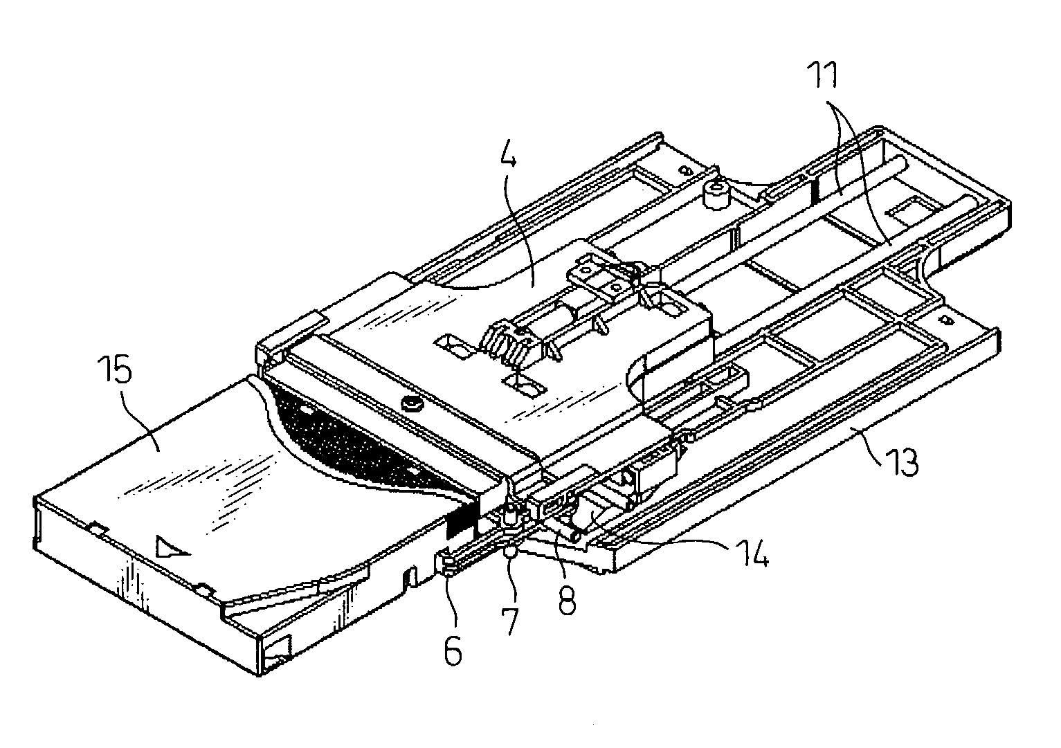
[0172]FIG. 27A is a view of the picker 4 shown in FIG. 17A in which the picker 4 is broken down into a mounter 21 and a picker main body 23, and FIG. 27B is a view of the mounter 21 taken from the bottom side. The picker main body 23 is a part to which the members described above such as the hooks 6, the pins 7, the slide shafts 8, the stoppers 9, the springs 10, the coupling portions 12 through which the slide shafts 11 are inserted, the actuators 16 and the springs 18 are attached. A middle bottom part 23a is provided at the upper side of these members of the picker main body 23 and on the middle bottom part 23a, another two slide shafts 24 are provided in the direction orthogonal to the s...

first embodiment

[0178]As the picker 4 goes further with the rotation of the motor 1, the elements are disposed in a relationship as shown in FIG. 30A. This positional relationship corresponds to the one in FIG. 21B in the embodiment using the actuators 16. In the first embodiment without the actuators 16, the pins 7 are disengaged from the guide 14 completely and the hooks 6 are closed due to the urging force of the springs 10. But, since the actuators 16 are used also in this embodiment, the hooks 6 still remain open.

[0179]As the picker 4 goes further, the elements are disposed in a relationship as shown in FIG. 30B. This positional relationship corresponds to the one in FIG. 22A in the embodiment using the actuators 16. Thus, the advance of the actuators 16 is stopped by the actuator abutting surfaces 20 of the cartridge accommodating rack 19 and the hooks 6 are closed as a result of movement of the pins 7 in the L-shaped grooves 17a in this state. At this time, the pins 7 are disengaged from pin...


PUM


Abstract

A robot hand that does not depend on cartridge types wherein high reliability can be ensured and the size and cost can be reduced with a simple construction. In a library apparatus including a recording and reproducing device for cartridge type media and cartridge accommodating racks, a robot hand is configured to include a hand mechanism including hooks for holding the cartridge and actuators for performing to and fro movement and opening and closing movement of the hooks, and a mounter for pushing the cartridge when the cartridge is inserted into the recording and reproducing device by the hand mechanism, wherein the to and fro movement and the opening and closing movement of the robot hand and the pushing movement of the mounter is performed by one motor. The cartridge is grasped/released efficiently by the movement of the hooks, the actuators and the mounter.

Description

CROSS-REFERENCE TO RELATED APPLICATION[0001]This application claims priority from, and incorporates by reference the entire disclosure of, Japanese Patent Application No. 2002-207260, filed on Jul. 16, 2002.BACKGROUND OF THE INVENTION[0002]1. Field of the Invention[0003]The present invention relates to a robot hand and a library apparatus and, in particular, it relates to a robot hand provided in a library apparatus wherein the library apparatus is connected to a computer and the like via a network. The library apparatus in the present invention can hold a plurality of cartridges, that have a magnetic tape and the like therein, inside the apparatus, and can record and reproduce information on the cartridge. The robot hand in the present invention can move the cartridge in the apparatus.[0004]2. Description of the Related Art[0005]Conventionally, as the amount of information increases in a computer system, there is provided an information storage device for storing a large amount of ...

Claims


Application Information

Patent Timeline
IPC IPC(8): G11B15/68G11B17/08G11B17/22G11B17/26
CPCG11B17/225G11B15/6835
Inventor YAMAKAWA, KENGOAOKI, KENJI
Owner FUJITSU LTD
Why Eureka
Try Eureka