Angle-based method and device for protecting a rotating component

a protection device and rotating component technology, applied in maintenance and safety accessories, food science, applications, etc., can solve problems such as damage, wear on the inside of grinding mills, and damage to rotating components. the effect of damage prevention

Inactive Publication Date: 2006-03-28
TIRSCHLER EHRENFRIED ALBERT
View PDF3 Cites 11 Cited by
  • Summary
  • Abstract
  • Description
  • Claims
  • Application Information

AI Technical Summary

Benefits of technology

[0025]Advantages of the present invention include that the proposed angle-based protection device and method is intended to prevent angle-based potentially damaging conditions from damaging rotating components. For example, the proposed angle-based protection device and method can be used for preventing a solidified mass within a conventional grinding mill from impacting the mill and damaging the latter upon rotation of the mill drum. The proposed device may also be used for preventing damages caused by actual load torque and designed torque mismatches or any other angle-based potentially damaging conditions.

Problems solved by technology

Because of particular physical phenomenons associated with rotating movements, rotating components part of various types of machines are subjected to particular operational parameters that may be potentially damaging especially when the rotating components reach critical angular values.
The potential for subjecting rotating components to damaging conditions is sometimes compounded when the rotating components are used for imparting a rotational movement to material contained therein, such as for mixing, grinding or other purposes.
In view of the abrasive character of the material being ground, the wear on the inside of the grinding mill has heretofore been a serious problem.
Some ores, such as taconite, are relatively highly abrasive.
Liners inevitably become worn and, hence, no longer effective.
This may prove to be detrimental to various components of the mill including the lining, heads and bearings thereof.
Also, since gear wheels are typically constructed with great accuracy, they may also be subjected to deformation by the impact.
The cost of the occurrence of such events is very burdensome.
Not only is the cost of material and repair involved extensive but the high capitalization costs of plants using large autogenous mills may be mobilized by extended non-productive down-time.
Another example of angle-dependent potentially damaging conditions may result from the potential mismatch between actual load and designed torques.
Also, sometimes the potentially damaging condition for the machine is concurrently more susceptible to happen upon the operational parameter meeting predetermined critical parameter conditions while the rotating component reaches a critical angular displacement value.
As mentioned previously, it is some times desirable to run the grinding mill at speeds considerably slower than the normal running speed.
However, such a prior art technique is not precise.
Furthermore, it is dangerous to personnel who may be installing or re-lining the mill as slings have a known tendency to break.
The switches, however, are relatively costly.
This partial clutch closure for long periods however generates considerable heat in the clutches and requires that the wet clutches be installed and provision made to dissipate the heat generated.
Also, typically, an installation using wet clutches is more expensive than one using dry clutches.

Method used


Image

  • Angle-based method and device for protecting a rotating component
  • Angle-based method and device for protecting a rotating component
  • Angle-based method and device for protecting a rotating component

Examples


Embodiment Construction

[0078]With reference to the annexed drawings a preferred embodiments of the present invention will be herein described for indicative purpose and by no means as of limitation.

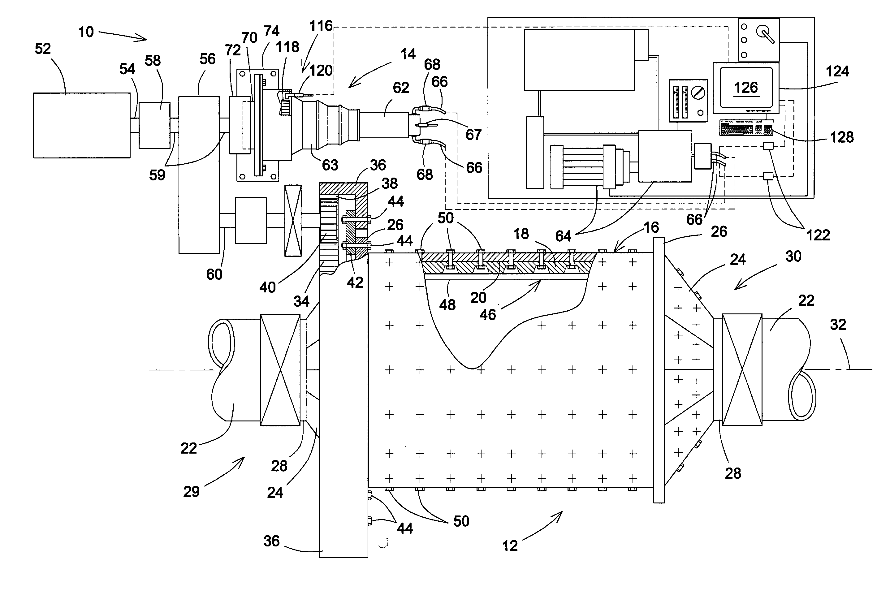
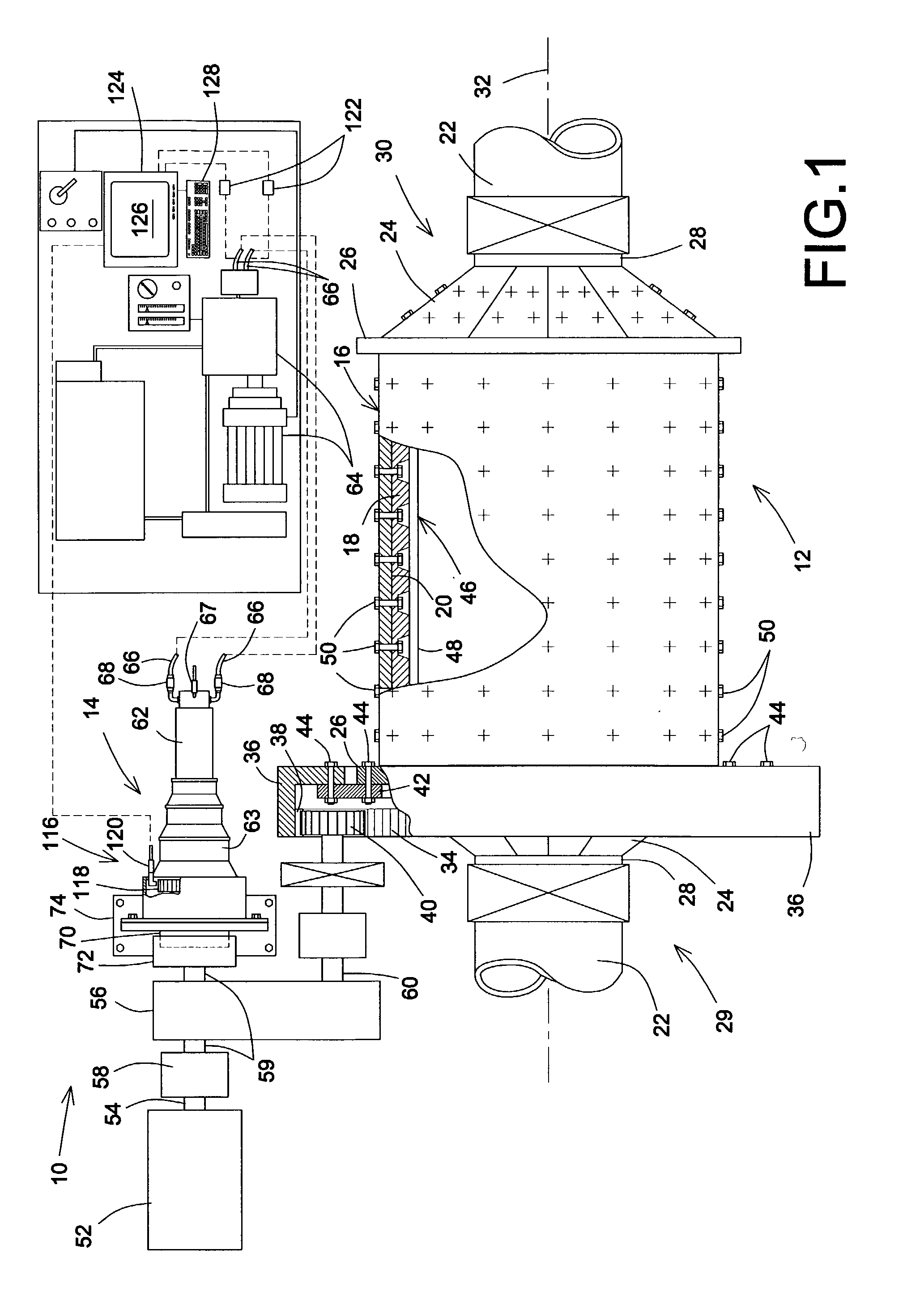
[0079]Referring to FIG. 1, there is shown a protection device generally indicated by reference numeral 10 in accordance with an embodiment of the present invention. The protection device 10 is shown being used with a conventional grinding mill 12 and a conventional hydraulic inching device 14. It should be understood that this type of installation merely represents one type of exemplary installation through which the concepts of the subject invention may be intended to be used and will allow those skilled in the art to more readily appreciate the general gist of the application for the proposed protection device. The protection device 10 may be used in other environments in conjunction with other types of machinery without departing from the overall intent or scope of the present invention.

[0080]The grinding mi...


PUM


Abstract

A method and device to protect a grinding mill used for grinding material therein by rotating the drum so that the material adheres to the drum inner surface and rises therewith over a cascading angle from a gravity-balanced condition prior to detach by gravity from the inner surface and tumble into a cascading flow. The method is used for protecting the grinding mill from damages potentially resulting from the material agglomerating into a generally solidified lumped volume that could adhere to the inner surface and rotate with the latter more than the cascading angle to a fail angle wherein the lumped volume may detach from the drum inner surface and impact an impact position within the drum.

Description

[0001]This application claims the benefit of Provisional Application 60 / 322,638, files Sep. 17, 2001.FIELD OF THE INVENTION[0002]The present invention relates to the general field of rotating machines and is particularly concerned with an angle-based protection device and method for protecting a rotating component part of a machine.BACKGROUND OF THE INVENTION[0003]The prior art is replete with various types of machines having rotating components for industrial, domestic, recreational and other purposes. Because of particular physical phenomenons associated with rotating movements, rotating components part of various types of machines are subjected to particular operational parameters that may be potentially damaging especially when the rotating components reach critical angular values. The potential for subjecting rotating components to damaging conditions is sometimes compounded when the rotating components are used for imparting a rotational movement to material contained therein,...

Claims


Application Information

Patent Timeline
Patent Type & Authority Patents(United States)
IPC IPC(8): B02C25/00B02C17/18B02C17/24B02C23/00B02C23/04
CPCB02C17/1805B02C25/00B02C23/04B02C17/24
Inventor TIRSCHLER, EHRENFRIED ALBERT
Owner TIRSCHLER EHRENFRIED ALBERT
Why Eureka
Try Eureka