
Active vibration control system

a technology of vibration control and vibration, applied in the direction of process and machine control, instruments, transportation and packaging, etc., can solve the problems of system failure, material fatigue, unwanted noise, etc., and achieve the effect of better control vibration and better vibration control

Inactive Publication Date: 2006-03-28
FOSTER-MILLER
View PDF14 Cites 33 Cited by
  • Summary
  • Abstract
  • Description
  • Claims
  • Application Information

AI Technical Summary

Benefits of technology

[0008]It is a further object of this invention to provide such an active vibration control system which requires less computational complexity.
[0009]It is a further object of this invention to provide such an active vibration control system which dampens vibrations even in chaotic systems.
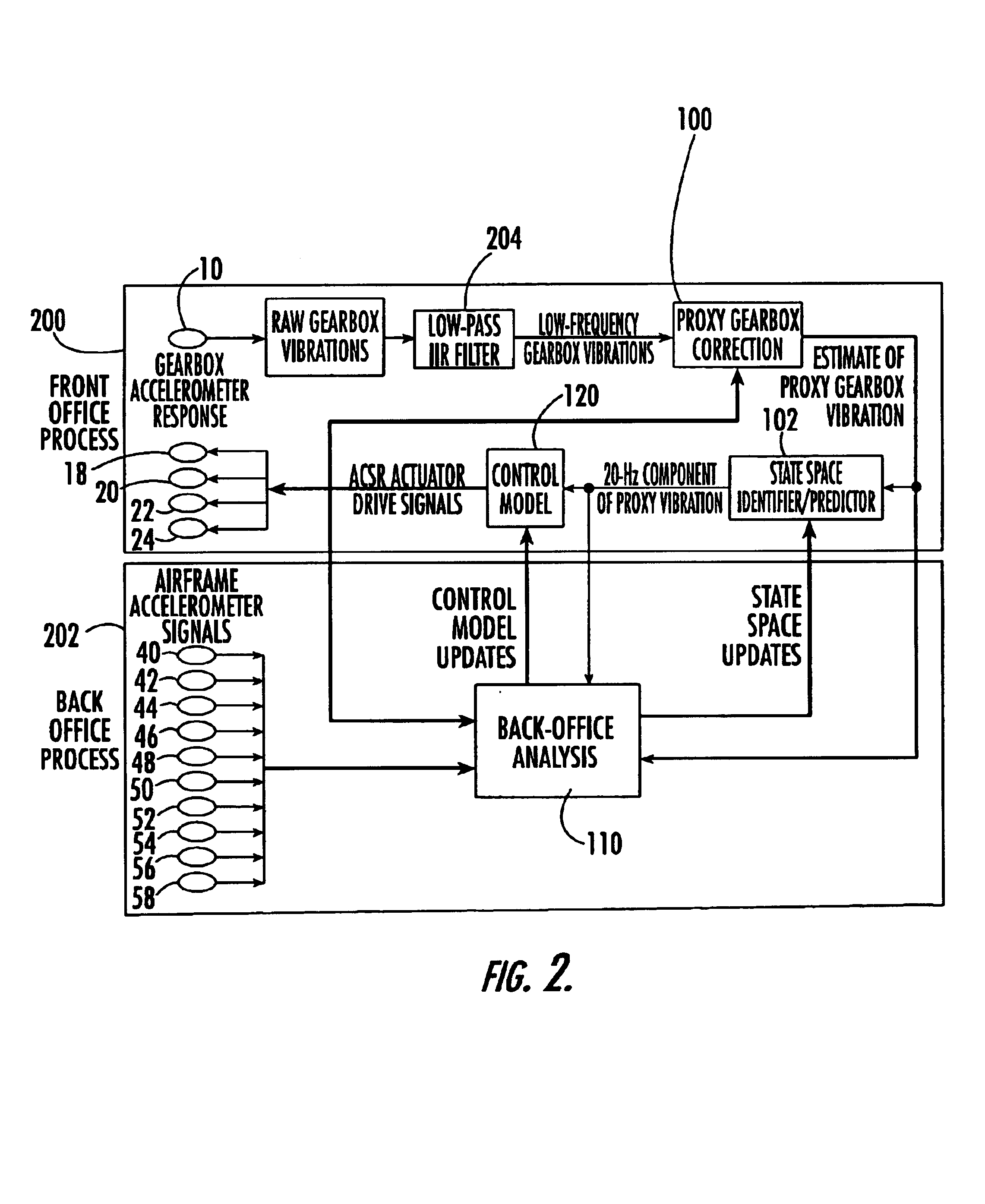
[0011]This invention results from the realization that the computational complexity of the prior art active vibration isolation systems can be reduced by a single accelerometer attached to the source of vibrations, a correction subsystem which estimates the output of that accelerometer in the absence of the controlling vibrations caused by the actuators and which drives the actuators according to the estimate thereby eliminating the need for numerous accelerometers on the structure and that even chaotic vibrations can be controlled a) by relying on the fact that they are deterministic and b) by employing a state space predictor which analyzes variations in the accelerometer's signal to better drive the actuators to control even chaotic vibrations.
[0012]This invention features an active vibration control system comprising a sensor responsive to a source of vibration which provides an output signal representative of the vibrations; at least one actuator positioned to impart canceling vibrations to the source of vibrations based on an input signal; a correction subsystem responsive to the actuator for estimating the sensor output in the absence of the canceling vibrations and which outputs a corrected output signal representative only of the vibrations emanating from the source; and a state space predictor responsive to the corrected output signal for determining the input signal to the actuator based on variations in the corrected output signal to better control vibrations especially in chaotic systems.
[0014]In one embodiment, the source of vibrations is the rotor, gear box, and engine assembly of helicopter, the sensor is an accelerometer attached to the gear box, and the actuator is positioned between the airframe of the helicopter and the rotor, gear box, and engine assembly. The improved active vibration control system of this invention includes a source of vibrations, a structure which is impacted by the source of vibrations, a sensor or sensors connected to the structure, an actuator or actuators positioned to impart canceling vibrations to the source; and an analyzer / control subsystem responsive to the sensor or sensors for driving the actuator or actuators. The improvement comprises a sensor to be positioned to detect vibrations directly from the source; and a software package including: a correction subsystem responsive to the actuator for estimating the sensor output in the absence of the canceling vibrations and which outputs a corrected output signal representative only of the vibrations emanating from the source; and a state space predictor responsive to the corrected output signal for determining the input signal to the actuator based on variations in the corrected output signal to better control vibrations especially in a chaotic system. The active vibration control system of this invention includes a sensor responsive to a source of vibration which provides an output signal representative of the vibrations; at least one actuator positioned to impart canceling vibrations to the source of vibrations based on an input signal; and a correction subsystem responsive to the actuator for estimating the sensor output in the absence of the canceling vibrations and which outputs a corrected output signal representative only of the vibrations emanating from the source. A sensor is responsive to a source of vibration which provides an output signal representative of the vibrations. At least one actuator is positioned to impart canceling vibrations to the source of vibrations based on an input signal. A state space predictor is responsive to the output signal for determining the input signal to the actuator based on variations in the output signal to better control vibrations especially in chaotic systems.

Problems solved by technology

Vibrations can cause unwanted noise, material fatigue, and even catastrophic failure of systems.
There are two primary problems associated with this and other prior art active vibration control systems.
The first is complexity.
Processing all the accelerometer signals and then deciding how to properly drive the actuators in response is very difficult and results in severe computational complexity.
The result is that present systems do not always sufficiently cancel the resulting vibrations when employed with sources of vibrations exhibiting irregular chaotic behavior.

Method used


Image

  • Active vibration control system
  • Active vibration control system
  • Active vibration control system

Examples


Embodiment Construction

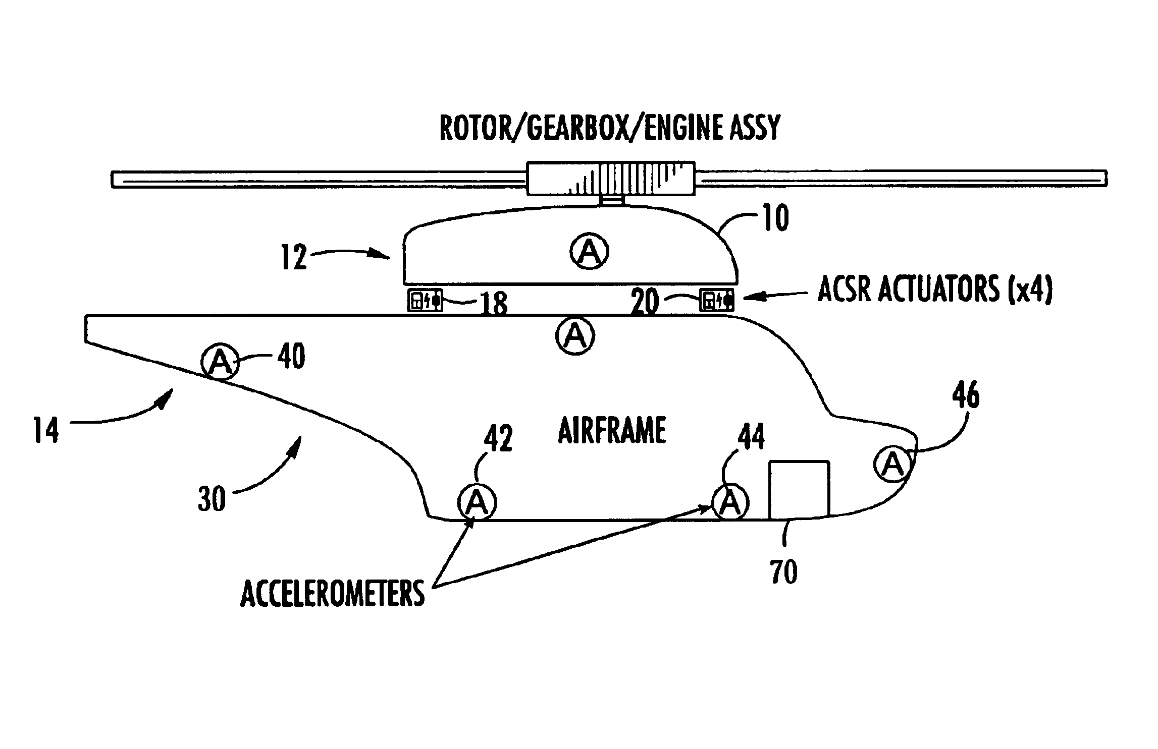
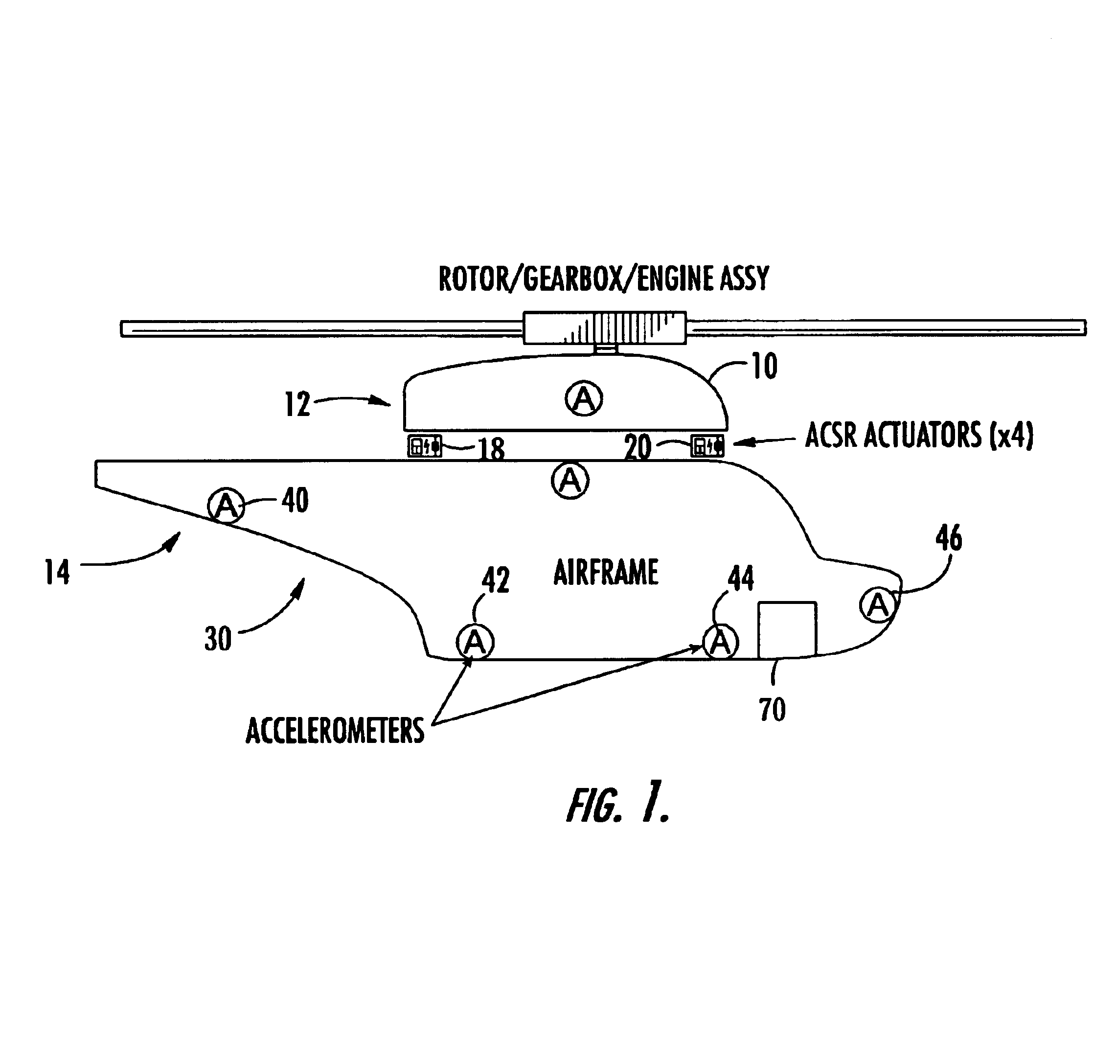
[0034]The active vibration control system of this invention features sensor 10, FIG. 1 responsive to a source of vibration. In this example, sensor 10 is an accelerometer attached directly to the gear box of the rotor, gear box, and engine assembly 12 of helicopter 14. Typically four electro-hydraulic actuators are used to impart canceling vibrations to the source of vibrations, engine assembly 12. In FIG. 1, two actuators 18 and 20 are shown between rotor, gear box, and engine assembly 12 and airframe 30, the structure to be isolated from vibrations caused by the rotor gear box, and the engine assembly of helicopter 14.

[0035]In the prior art, no accelerometer is attached directly to the source of vibrations and instead accelerometers 40, 42, 44, and 46 (and others) are used as the input to controller 70 on board helicopter 14 which drives actuators 18 and 20. The reason is that the signal from accelerometer 10 depends not only on the vibrations emanating from source 12, but also on...


PUM


Abstract

An active vibration control system including a sensor responsive to a source of vibration and which provides an output signal representative of the vibrations; at least one actuator positioned to impart canceling vibrations to the source of vibrations based on an input signal; a correction subsystem responsive to the actuator for estimating the sensor output in the absence of the canceling vibrations and which outputs a corrected output signal representative only of the vibrations emanating from the source; and a state space predictor responsive to the corrected output signal for determining the input signal to the actuator based on variations in the corrected output signal to better control vibrations especially in chaotic systems.

Description

GOVERNMENT RIGHTS LEGEND[0001]The invention was made in part under Government Contract No. NOO421-96-C-1120. The U.S. Government may have certain rights in this invention.FIELD OF THE INVENTION[0002]This invention relates to an active vibration control system useful, for example, to control vibrations caused by the rotor, gear box, and engine assembly of a helicopter and to isolate structures from sources of vibration.BACKGROUND OF THE INVENTION[0003]Vibrations can cause unwanted noise, material fatigue, and even catastrophic failure of systems. In response, active vibration control systems are sometimes employed. In general, the control system detects the amplitude and frequency of the vibrations emanating from a vibrating source and attempts to cancel them out by imparting canceling forces.[0004]In one prior art system, vibrations of the rotor, gear box, and engine assembly of a helicopter (e.g., the Westland-Agusta EH-101 Merlin helicopter) are controlled by a system including ac...

Claims


Application Information

Patent Timeline
IPC IPC(8): B64C27/51G05D19/02
CPCG05D19/02B64C2027/004
Inventor HILL, WAYNETSIMRING, LEV S.
Owner FOSTER-MILLER
Learn More