Supercharge Your Innovation With Domain-Expert AI Agents!

Solenoid valve

a solenoid valve and valve body technology, applied in the direction of valve operating means/release devices, machines/engines, transportation and packaging, etc., can solve the problem of difficult inspection of the seal member b

Inactive Publication Date: 2006-03-28
EAGLE INDS
View PDF8 Cites 12 Cited by
  • Summary
  • Abstract
  • Description
  • Claims
  • Application Information

AI Technical Summary

Benefits of technology

Enables reliable detection of seal member damage or defects during assembly, ensuring the sealability of the solenoid valve and preventing fluid leakage and contamination during use.

Problems solved by technology

Therefore, even when an air-tightness test is conducted at the time of completion of the production of the solenoid valve assembly, it is difficult to examine the seal member 104 whether or not there are damage to, bite into and a defect of the seal member 104.

Method used


Image

  • Solenoid valve
  • Solenoid valve
  • Solenoid valve

Examples


Embodiment Construction

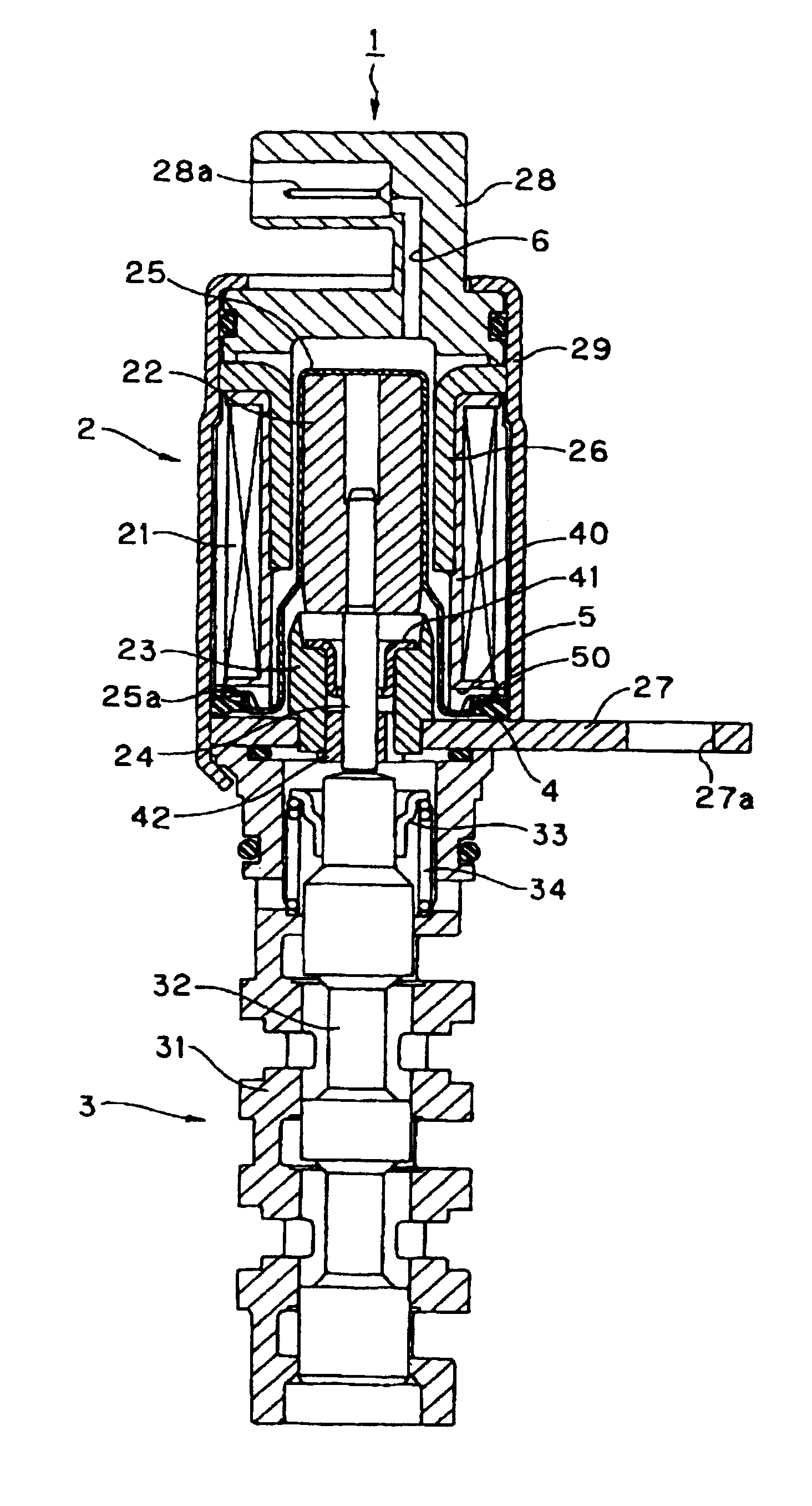
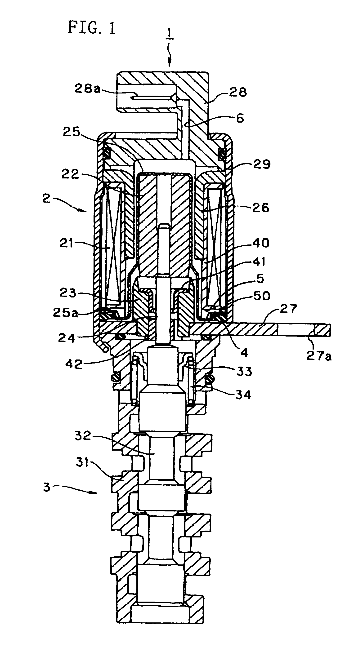
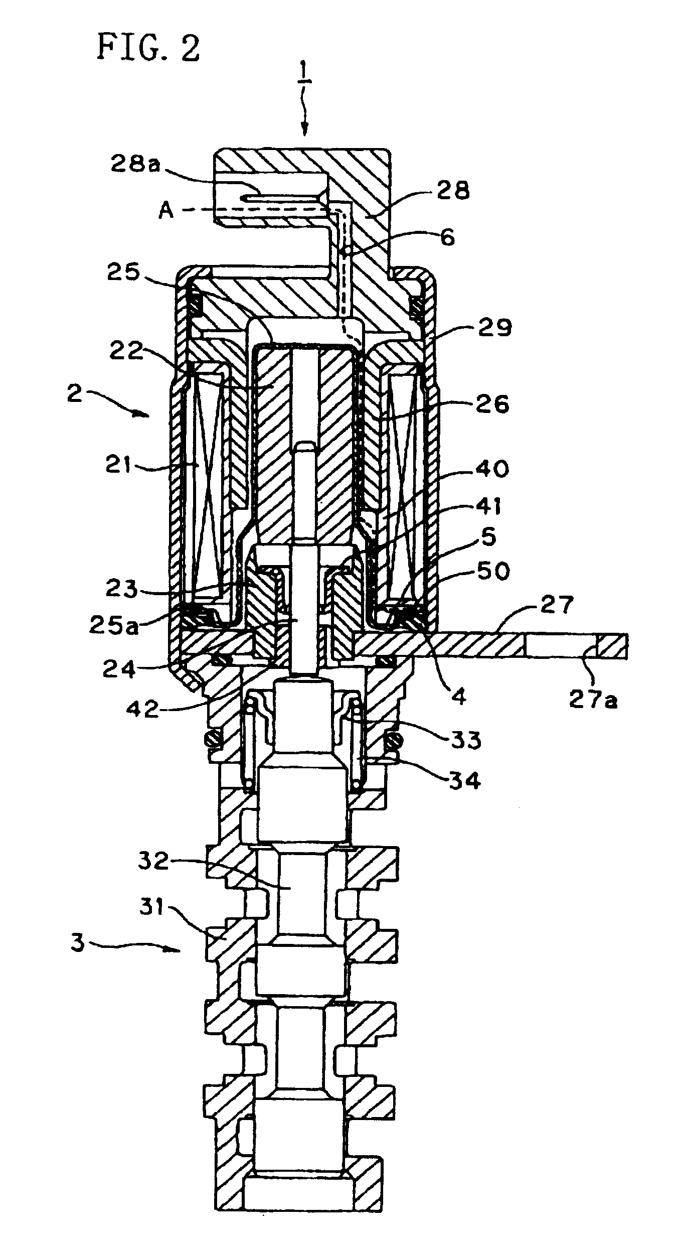
[0032]An embodiment of the solenoid valve according to the present invention will be described with reference to FIGS. 1 to 2. FIG. 1 is a sectioned schematic construction diagram of the embodiment of the solenoid valve. FIG. 2 is a sectioned schematic construction diagram of the embodiment of the solenoid valve, showing a passage reaching a seal member.

[0033]A solenoid valve 1 includes a solenoid portion 2 and a valve portion 3.

[0034]Here, in the illustrated example, the valve portion 3 is a spool valve. In the interior of a valve sleeve 31, a spool 32 is provided so that the spool 32 can be reciprocatingly moved. Since a cross-sectional area of an opening of a valve formed in the valve sleeve 31 varies in accordance with a stroke of the spool 32, an inflow rate and an outflow rate of a fluid can be controlled through a control operation for a quantity of a stroke of the spool 32 by the solenoid portion 2.

[0035]The solenoid portion 2 is provided with a substantially cylindrical coi...


PUM

PropertyMeasurementUnit
magnetic fieldaaaaaaaaaa
electric poweraaaaaaaaaa
pressuresaaaaaaaaaa

Abstract

In the region in which a coil and a connector are provided, the leakage of a fluid to which coil and connector is prevented by a seal member, a passage extending from the seal member to a position in the vicinity of a terminal of the connector is formed. At the time of completion of the production of a solenoid valve assembly, an air-tightness test on the seal member can be conducted directly through the passage, so that the detection of damage to the seal member, the detection of bite into the seal member, the detection of a defect of the seal member and so on can be carried out at the time of completion of the production of the mentioned assembly. Namely, the detection of the sealability of the seal member is rendered possible.

Description

BACKGROUND OF THE INVENTION[0001]1. Field of the Invention[0002]This invention relates to a solenoid valve used to control the pressures of various kinds of fluids.[0003]2. Description of the Related Art[0004]The conventional art solenoid valves of this kind include, for example, a solenoid valve shown in FIG. 3. FIG. 3 is a sectioned schematic construction diagram of this conventional art solenoid valve.[0005]A solenoid valve 101 includes a solenoid portion 102 and a valve portion 103.[0006]Here, in the illustrated example, the valve portion 103 is a spool valve. In the interior of a valve sleeve 131, a spool 132 is provided so that the spool 132 can be reciprocatingly moved. Since a cross-sectional area of an opening of a valve formed in the valve sleeve 131 varies in accordance with a stroke of the spool 132, an inflow rate and an outflow rate of a fluid can be controlled through a control operation for a quantity of a stroke of the spool 132 by the solenoid portion 102.[0007]The...

Claims


Application Information

Patent Timeline
Patent Type & Authority Patents(United States)
IPC IPC(8): F16K31/02F01L1/34F16K31/06H01F7/08
CPCH01F7/08F16K31/0668F16K31/0613F01L2001/34436Y10T137/5987
Inventor HIRATA, ICHIRONAGAYOSHI, KAZUAKIONO, AKIRAHORA, MAKOTOKASAGI, YOSHINARI
Owner EAGLE INDS
Features
  • R&D
  • Intellectual Property
  • Life Sciences
  • Materials
  • Tech Scout
  • Unparalleled Data Quality
  • Higher Quality Content
  • 60% Fewer Hallucinations
Learn More