Flexible corrugated hose fitting

a flexible corrugated hose and fitting technology, applied in the direction of hose connection, other domestic objects, mechanical apparatus, etc., can solve the problems of large amount of imperviousness, partial damage of flexible corrugated hose, and the inability to make welded connections with a considerable apparatus investment, etc., to achieve the effect of simple technical means and efficient process

Inactive Publication Date: 2006-03-28
EATON FLUID POWER GMBH
View PDF12 Cites 38 Cited by
  • Summary
  • Abstract
  • Description
  • Claims
  • Application Information

AI Technical Summary

Benefits of technology

[0009]By means of the flexible corrugated hose fittings according to the present invention, it is possible to prepare a free end of a flexible corrugated hose in a pressure-proof and permanently sealed manner for connection with further devices. The hose lengths which can be produced here can be set depending on the requirements and independently of production-related hose lengths. The flexible corrugated hose fittings allow the retroactive connection to the open end of a flexible corrugated hose without soldering and welding operations and by simple technical means, which can be made available by the user. Therefore, when installing flexible corrugated hoses into its fluid-conducting systems, the user does not have to rely on having to buy ready-made flexible corrugates hoses from the manufacturer, but he can also fall back on endless material and can cut the flexible corrugated hoses to size as needed. This allows the particular option of the usage in small and very small series. Further than that, an efficient process is made possible, even with industrial scale manufacture.
[0010]The flexible corrugated hose fitting according to an embodiment of the present invention, has a connecting element with an extension, which is pushed into the corrugated pipe and which secures the connecting element interlockingly in the corrugated pipe. The securing means provided on the extension utilize the interior shape of the corrugated pipe for the interlocking securing. A connection of tensile strength, which can be greatly stressed in the axial direction, between the connecting element and the corrugated pipe is created by means of this, so that fluid pressures acting in the corrugated pipe cannot result in the release of the connection.

Problems solved by technology

The introduction of such flexible corrugated hoses into pressure-carrying systems is not without problems, in particular if large mechanical stresses and / or large stresses due to pressure must be expected and a great amount of imperviousness is required.
Welded connections between other types of lines and the corrugated pipe also always involve a thermal stress of the surroundings, which can lead to partial damages of the flexible corrugated hose.
Moreover, welded connections can only be made with a considerable outlay in apparatus.
Occasionally the problem arises of having to provide flexible corrugated hoses in lengths in accordance with their intended use.
Under bending stress, the heavy sheathing provided results in high tensile stress between the sheathing and the connection fittings.
Such tensile stresses must not be allowed to result in damage to the connection.

Method used


Image

  • Flexible corrugated hose fitting
  • Flexible corrugated hose fitting
  • Flexible corrugated hose fitting

Examples


Embodiment Construction

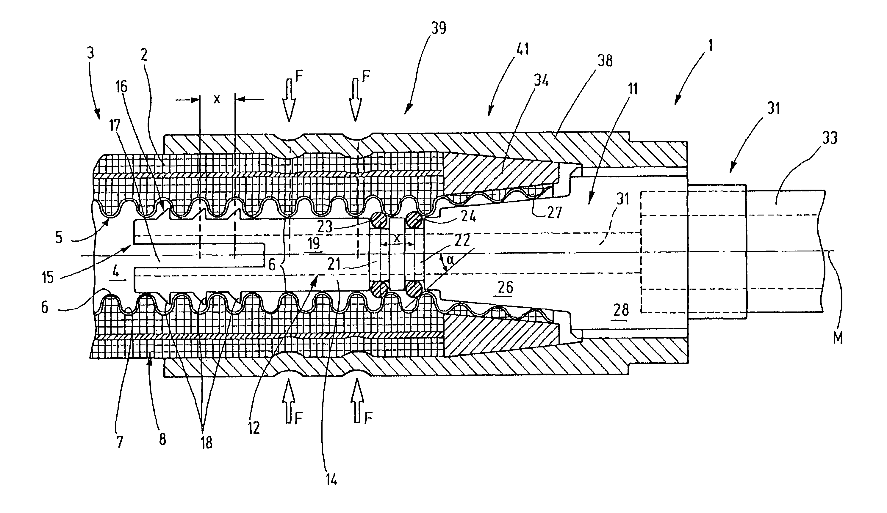
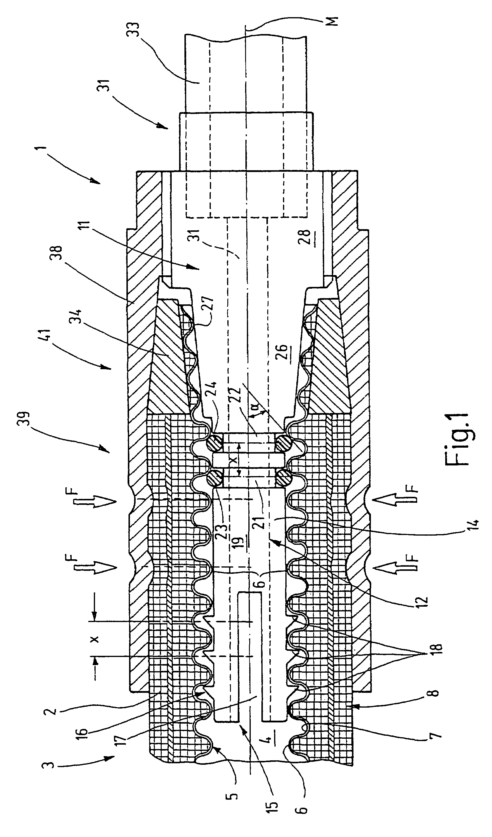
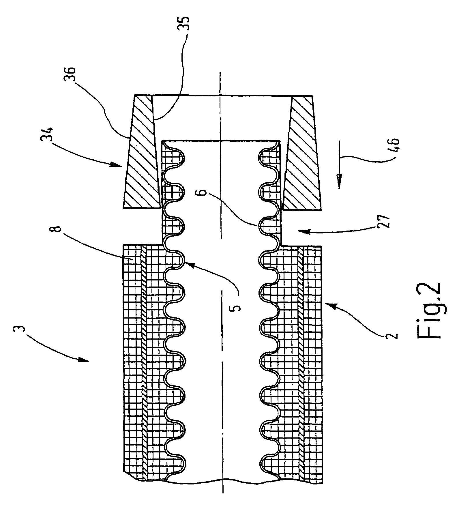
[0037]A flexible corrugated hose fitting 1 and an end 2 of a flexible corrugated hose 3 are represented in a longitudinal sectional view in FIG. 1. The flexible corrugated hose 3 has a central fluid channel 4, whose walls are constituted by a corrugated pipe 5. The corrugated pipe 5 is embodied in the way of a bellows, wherein the diameter of the corrugated pipe 5 changes in a wave shape along its axial direction. By means of this, inward oriented ribs 6 (narrowing the fluid channel 4) are created on the corrugated pipe 5 and define wave crests, so to speak, wherein a wave trough 7 is formed between two ribs 6. The corrugated pipe is made of a flexible material, special steel, for example, or some other metal. Preferably it is embodied as a welded pipe and therefore has a longitudinal bead, which is not represented in the drawing figures.

[0038]A sheathing 8 is seated on the corrugated pipe 5, which is essentially constituted by an elastomeric material, such a caoutchouc, plastic, si...


PUM

PropertyMeasurementUnit
cone angleaaaaaaaaaa
bursting pressuresaaaaaaaaaa
cone angleaaaaaaaaaa

Abstract

A flexible corrugated hose fitting, which is particularly provided for high-pressure installations, such as air conditioning installations using CO2 as the refrigerant, has a connecting element, which can be snapped together with the interior corrugated pipe of the flexible corrugated hose. In addition, the connecting element has sealing elements, which come into sealing contact with the corrugated pipe. Following the area receiving the sealing elements, the connecting element has a cone, which is used as a clamping section. An exterior squeeze ring, or other squeeze element, is used for pressing the exposed end of the corrugated pipe against the clamping section. A pressing sleeve is used for pressing, which drives the squeeze ring by a wedge effect inward. It has an appropriate conical interior surface. The squeeze ring moreover extends over the sheathing. For further securing of the connection, the pressing sleeve can be pressed together here with the sheathing by an appropriate deformation. The pressing sleeve can alternatively be provided with an interior thread in this area, which cuts into the sheathing.

Description

BACKGROUND OF THE INVENTION[0001]1. Field of the Invention[0002]The invention relates to a flexible corrugated hose fitting, in particular for flexible corrugated hoses having a corrugated pipe and a sheathing, for example of an elastomer, in particular for use in pressure-carrying systems.[0003]2. Description of the Related Art[0004]At times, flexible lines, which are provided by means of special hoses, are required in fluid-conducting systems. For example, such hoses are flexible corrugated hoses, such as are used for higher pressures. Flexible corrugated hoses have a corrugated pipe which is flexibly bendable because of its shape and encloses a fluid channel. The corrugated pipe is provided with a sheathing on its exterior, for example made of an elastomer. The sheathing can be reinforced by means of textile materials or a wire mesh.[0005]The introduction of such flexible corrugated hoses into pressure-carrying systems is not without problems, in particular if large mechanical st...

Claims


Application Information

Patent Timeline
Patent Type & Authority Patents(United States)
IPC IPC(8): F16L47/00F16L21/04F16L21/06F16L25/00F16L33/00F16L33/01F16L33/207F16L33/22F16L33/28
CPCF16L25/0036F16L33/2076F16L33/222Y10T29/49428Y10S285/903
Inventor LUFT, THOMASSCHNEIDER, AXELHUCK, MICHAEL MARKUSTWARDAWSKI, HARALD
Owner EATON FLUID POWER GMBH
Why Eureka
Try Eureka