Shock absorption pad for a vehicle

a technology for shock absorption pads and vehicles, applied in the direction of roofs, cycle equipment, pedestrian/occupant safety arrangements, etc., can solve the problems of increased cost, inability to absorb the deformation process of the vehicle body at the time of a vehicle crash, and the magnitude of the impact load

Inactive Publication Date: 2006-03-28
TOYOTA JIDOSHA KK +2
View PDF41 Cites 12 Cited by
  • Summary
  • Abstract
  • Description
  • Claims
  • Application Information

AI Technical Summary

Benefits of technology

[0017]Additionally, in the case of the shock absorption pad being a foam-molded component made from a styrene modified polyethylene resin, advantageous effects resulting from the characteristic peculiar to styrene modified polyethylene resin, such as outstanding dimensional stability and form retention characteristic, good shock absorption characteristic, and the characteristic of being difficult to generate wear powder and undesired noise against rubbing, can be gained.

Problems solved by technology

However, giving a desired shock absorbent function to the structure of the vehicle itself involves design changes of vehicle body structure and may require additional material and parts to achieve the desired shock absorbent function.
So it is predicted to increase the cost.
Moreover, in the case of using a shock absorption material, such as a foam material, since the shock absorption characteristic is fixed, the impact load whose magnitude varies in the deformation process of the vehicle body at the time of a vehicle crash cannot be absorbed effectively.
However, it is difficult to achieve adequate compatibility between this reduction and the reduction of the impact force which becomes suddenly high for a short time interval in the boundary region at which the energy absorption load of the vehicle body changes.
However, this will result in increased manufacturing cost of the body structure.

Method used


Image

  • Shock absorption pad for a vehicle
  • Shock absorption pad for a vehicle
  • Shock absorption pad for a vehicle

Examples


Embodiment Construction

[0029]Hereafter, the preferred embodiments according to the present invention are explained with reference to the drawings.

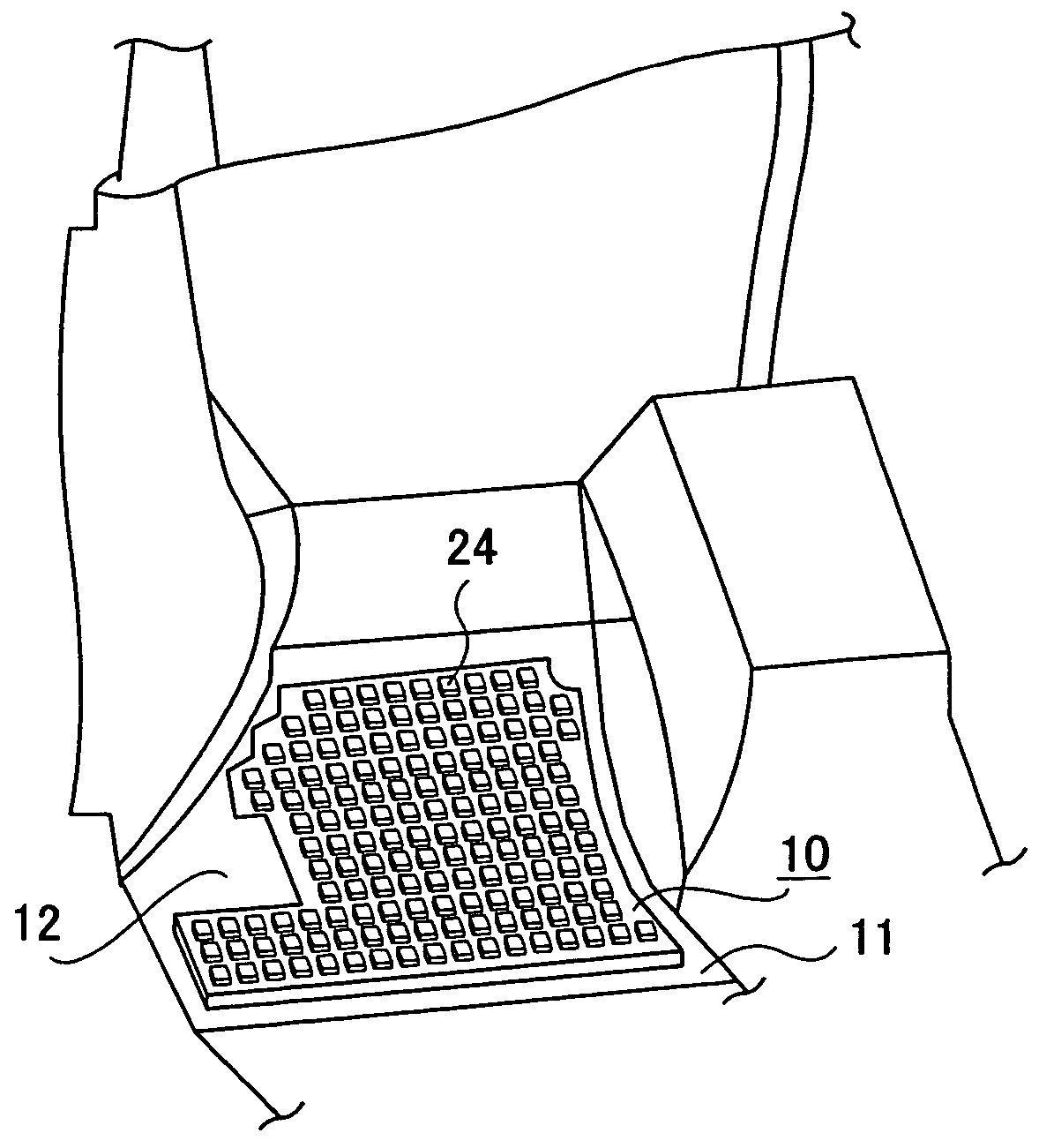
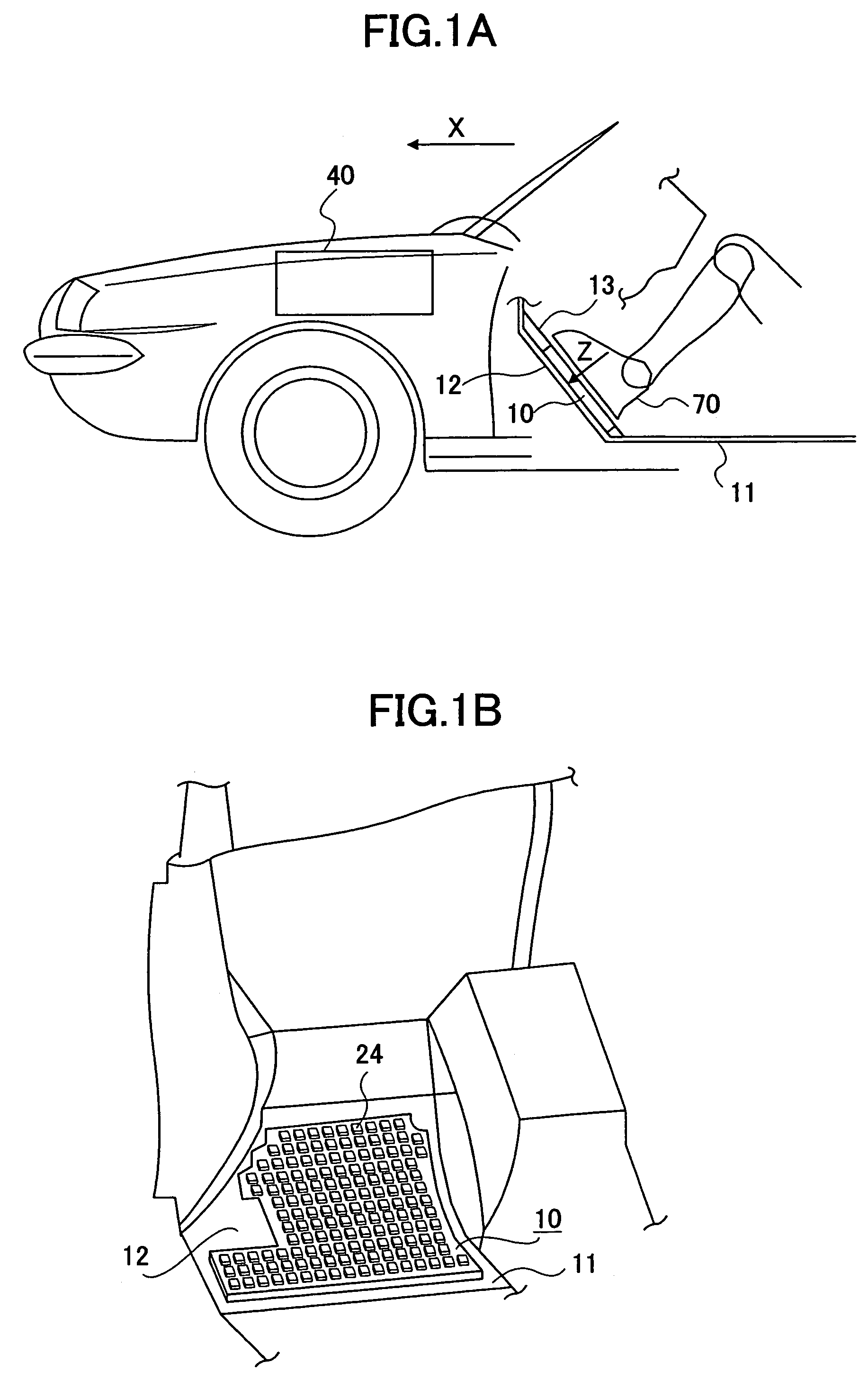
[0030]FIG. 1A is a cross-sectional view for diagrammatically illustrating the shock absorption pad 10 according to the present invention, which is assembled in a vehicle body in place, seen from the vehicle side. FIG. 1B is a perspective view for illustrating the installed shock absorption pad 10 in more detail.

[0031]The shock absorption pad 10 is disposed on a toe board 12 that extends forward and upward in a slanting direction from the front end of the floor panel 11 (arrow X shown in FIG. 1A indicates the front direction). The toe board 12 defines an inclined area (hereafter, this inclined area is referred as “foot-placing area”) on which occupant's legs 70 are to be placed, as shown in FIG. 1A. Generally, the shock absorption pad 10 is placed in the above-mentioned foot-placing area of the toe board 12 and attached to the toe board 12 with clips, etc. Genera...


PUM


Abstract

The present invention the related to a shock absorption pad for a vehicle for protecting occupant's lower legs. The shock absorption pad according to the present invention on which an occupant's foot is placed is attached on a surface of a toe board. The shock absorption pad includes a first shock absorption layer provided on the occupant's foot-placing side for absorbing an impact generated in a boundary region at which an energy absorption load of a vehicle body becomes different in a deformation process of the vehicle body at a vehicle crash, and a second shock absorption part provided on the toe board's side for absorbing an impact generated in a region in which the energy absorption load is high.

Description

TECHNICAL FIELD[0001]The invention relates to a shock absorption pad for use in a vehicle for protecting occupant's lower legs at the time of a vehicle crash, and more specifically relates to a shock absorption pad for use in a vehicle having a stepwise shock absorption characteristic.BACKGROUND ART[0002]Concerning the structure for protecting occupant's lower legs, JP, 2000-103367, A and JP, 2000-326870, A disclose inventions, wherein the structure of a vehicle itself is configured to have the desired shock absorption characteristic. Further, JP, 5-330341, A and JP, 6-17097, B, disclose inventions, wherein the foam material that absorbs energy is arranged in foot resting portions in the cabin so as to protect the occupant's lower legs.[0003]However, giving a desired shock absorbent function to the structure of the vehicle itself involves design changes of vehicle body structure and may require additional material and parts to achieve the desired shock absorbent function. So it is p...

Claims


Application Information

Patent Timeline
Patent Type & Authority Patents(United States)
IPC IPC(8): B60N3/06B60R21/04B60R21/00
CPCB60N3/066B60R21/04B60R2021/0414B60R2021/0046B60N3/00B60N3/06B60R21/00
Inventor MURAKAMI, TAKESHIFUKUYAMA, TAKUOKADA, TAKAHARU
Owner TOYOTA JIDOSHA KK
Why Eureka
Try Eureka