Electrical insulation layer and battery device

a battery device and electric insulation technology, applied in the field of electric insulation layer and battery device, can solve the problems of unsatisfactory ion conductivity at room temperature, shrinkage of separator at high temperature, generation of electric short circuit, etc., and achieve excellent electrical insulation excellent battery properties, excellent ion conductivity

Active Publication Date: 2015-06-04
SEKISUI CHEM CO LTD +1
View PDF1 Cites 13 Cited by
  • Summary
  • Abstract
  • Description
  • Claims
  • Application Information

AI Technical Summary

Benefits of technology

[0015]The electrical insulation layer of the present invention exhibits excellent electrical insulation properties, ion conductivity, mechanical strength and retention of the electrolyte solution. Therefore, by using the electrical insulation layer as a separator for preventing short circuit of the anode and the cathode of the battery, a battery device exhibiting excellent battery properties can be obtained.
[0016]The battery device of the present invention exhibits excellent volume retention and hardly suffers generation of bias of the electrolyte solution inside the battery. Therefore, the battery device of the present invention is preferable in stationary applications in houses and plants and electric vehicle applications.

Problems solved by technology

In a conventional lithium ion secondary battery device, in the case where a solid electrolyte is used, there was a problem that the ion conductivity was unsatisfactory at room temperature.
Further, in the case where an electrolyte solution or a gel electrolyte is used, by the use of a polyolefin separator, there were problems such as shrinkage of the separator at high temperatures and generation of electric short circuit caused by rapid charging or formation of lithium dendrites in a low temperature environment.
In addition, since a polyolefin separator does not have a high affinity for an electrolyte solution, the storage properties of the electrolyte solution become poor.
As a result, there was a problem that, when the position of the lithium ion secondary battery is fixed in a certain direction over a long time, the electrolyte solution inside the separator is biased, such that the battery cannot be charged / discharged.
This bias of the electrolyte solution becomes a serious problem especially in stationary applications in houses and plants and electric vehicle applications.

Method used


Image

  • Electrical insulation layer and battery device
  • Electrical insulation layer and battery device
  • Electrical insulation layer and battery device

Examples


example 1-1

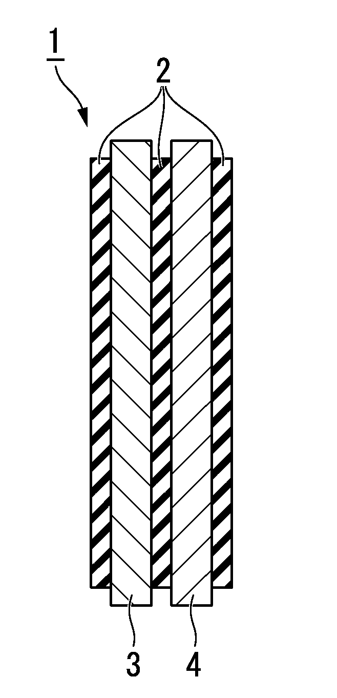
Production of Electrical Insulation Layer

[0173]20 g of the polymethylurea was dispersed in 80 g of a deionized water while applying a medium shear force, thereby obtaining a slurry. In the slurry, microparticles (average particle diameter: about 3.5 μm to 6.5 μm) composed of polymethylurea agglomerated were dispersed. Hereafter, these microparticles are sometimes referred to as PMU microparticles.

[0174]4 g of polyvinylalcohl (manufactured by Sigma-Aldrich, average molecular weight: 146,000 to 186,000, 87 to 89% hydrolysis) was dissolved in the deionized water in advance, thereby preparing a 10 wt % aqueous solution. Then, the polymethylurea slurry and the polyvinyl alcohol aqueous solution were mixed together, followed by stirring mildly with a magnetic stirrer for 10 minutes. The operation heretofor was conducted at 25° C.

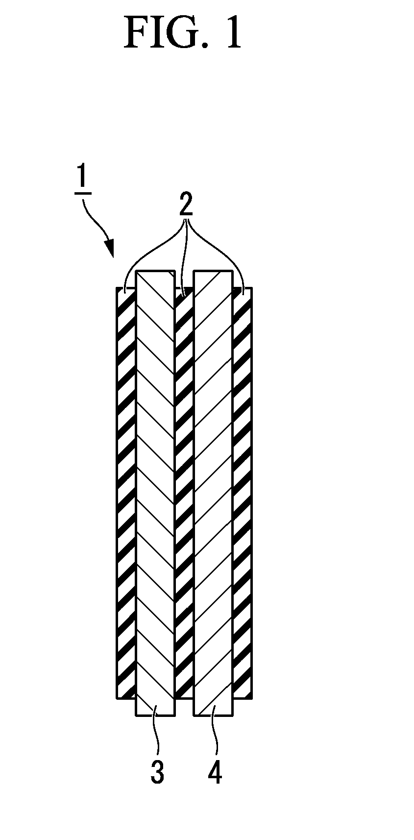
[0175]Using a No. 50 Meyer Rod, the above obtained mixture (electrical insulation layer composition) was coated on a copper foil with a thickness of 25 μm. Then, ...

example 1-2

Production of Electrolyte

[0181]17 g of the polymethylurea was dispersed in 68 g of a deionized water while applying a medium shear force e, thereby obtaining a slurry. In the slurry, the PMU microparticles are dispersed.

[0182]4 g of polyvinylalcohl (manufactured by Sigma-Aldrich, average molecular weight: 146,000 to 186,000, 87 to 89% hydrolysis) was dissolved in the deionized water in advance, thereby preparing a 10 wt % aqueous solution.

[0183]Subsequently, the polymethylurea slurry was mixed with 10 g of an aqueous solution in which silica gel particles (“Sylojet 30A” manufactured by Grace Davison; silica average particle diameter: 0.3 μm; pore volume: 0.72 ml / g; silica surface area: 171 m2 / g; porosity: 61.3 vol %; internal pore size: 20 nm to 50 nm) as nanoparticles were dispersed with a concentration of 30 wt %. Further, the above polyvinyl alcohol aqueous solution was added thereto, followed by stirring mildly with a magnetic stirrer for 10 minutes. The operation heretofor was ...

example 1-20

[Example 1-3] to [Example 1-20]

[Comparative Example 1-1] to [Comparative Example 1-4]

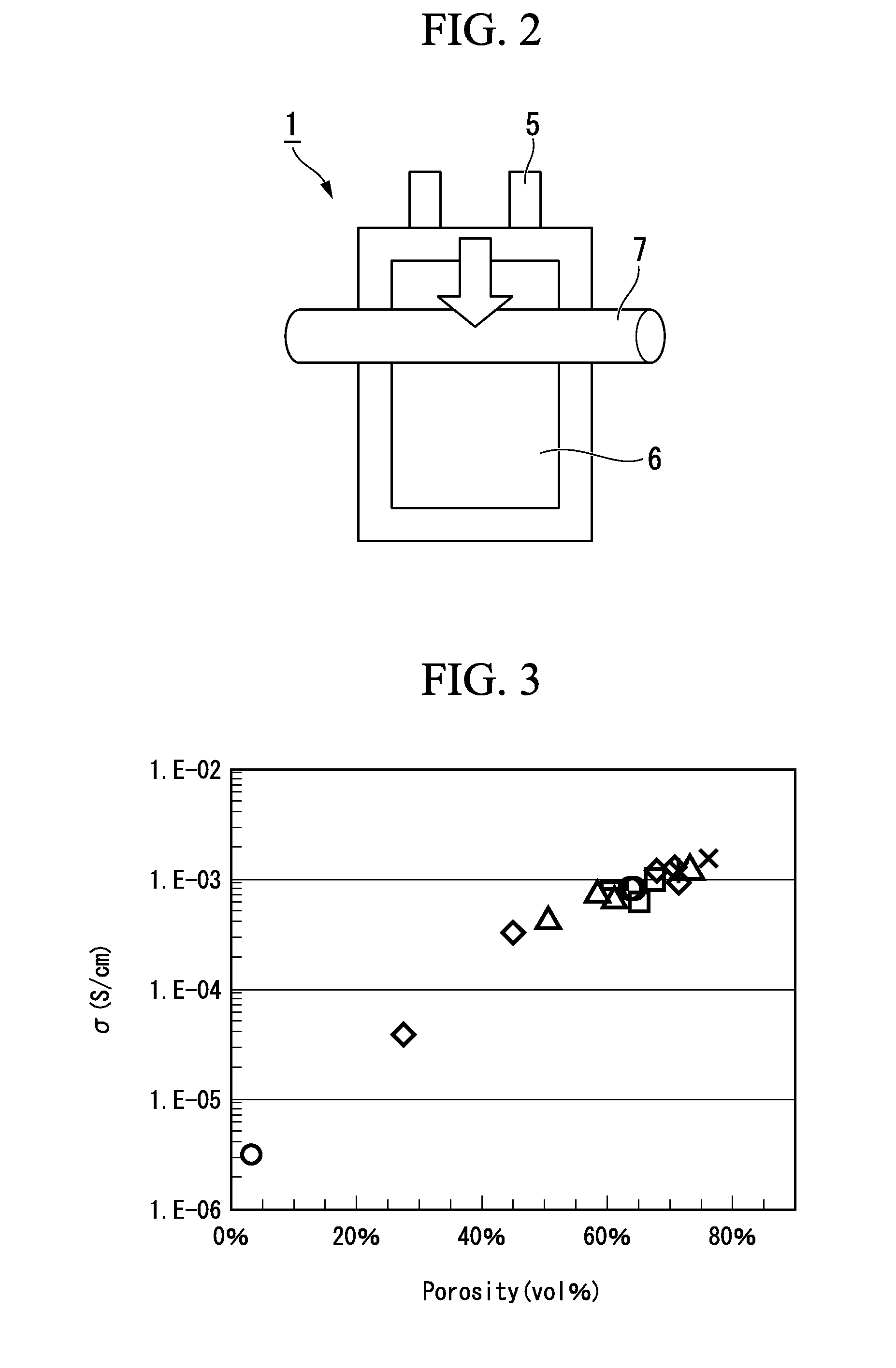
[0187]An electric insulation layer and an electrolyte in which microparticles and nanoparticles were blended with a weight ratio shown in the table below were produced in the same manner as in [Example 1-1] or [Example 1-2]. The evaluation of the mechanical strength of the electrical insulation layer, the analysis of the porosity and the pore distribution and the measurement of the ion conductivity of the obtained electrolyte were conducted in the same manner as in Example 1-1. The results are shown in the table below.

TABLE 1MicroparticlesNanoparticlesBinder solutionsTotal of(weight ratio)(weight ratio)(weight ratio)weight ratioExample 1-1PMU M6—PVA aqueous solution120(100)(0)(20)Example 1-2PMU M6SiO2 A30PVA aqueous solution120(85)(15)(20)Example 1-3PMU M6SiO2 A30PVA aqueous solution120(70)(30)(20)Example 1-4PMU M6SiO2 A30PVA aqueous solution120(55)(45)(20)Example 1-5PMU M6SiO2 A30PVA aqueous soluti...


PUM

PropertyMeasurementUnit
electrical insulationaaaaaaaaaa
total volumeaaaaaaaaaa
structureaaaaaaaaaa

Abstract

An electrical insulation layer including microparticles and having a mesoporous structure; and a battery device including a cathode, an anode, an electrical insulation layer including microparticles and having a mesoporous structure, the electrical insulation layer being arranged between the anode and the cathode, and an ion conductive composition.

Description

FIELD OF THE INVENTION[0001]The present invention relates to an electrical insulation layer exhibiting an excellent ion conductivity, and a battery device provided with the electrical insulation layer.DESCRIPTION OF RELATED ART[0002]Conventionally, between a cathode and an anode constituting a lithium ion secondary battery, a porous membrane having an electrolyte impregnated is used as a separator. However, lithium dendrites having a large surface area is formed, which may become a cause of an electric short circuit within the battery. As a method of preventing the short circuit, there are known a method in which the material for the anode is changed from a lithium metal to carbon black or the like in which lithium ion can be inserted, and a method in which a solid electrolyte is used. For example, as a matrix polymer constituting a solid electrolyte, homopolymers and copolymers of polyethylene oxide, polyacrylonitrile, polysiloxane and the like have been proposed (see Patent Litera...

Claims


Application Information

Patent Timeline
Patent Type & Authority Applications(United States)
IPC IPC(8): H01M2/16H01M10/0569H01M10/0568H01M50/403H01M50/414H01M50/434H01M50/491H01M50/497
CPCH01M2/164H01M10/0568H01M10/0569H01M2300/0028H01M2/1646H01M2300/0025H01M2/1653H01M10/0525Y02E60/10H01M50/403H01M50/446H01M50/46H01M50/491H01M50/414H01M50/434H01M50/497Y02T10/70H01M50/443H01M50/59H01M50/431H01M2220/20
Inventor TANG, YUYINGWATKINS, JAMESSHINMEI, KENICHIDASANAYAKE ALUTHGE, RASIKAKOIZUMI, SUSUMUKANOH, MASASHI
Owner SEKISUI CHEM CO LTD
Why Eureka
Try Eureka