System and method for correcting luminance non-uniformity of obliquely projected images

a technology of luminance and non-uniformity, applied in the field of electronic imaging systems, can solve problems such as the mechanism does not, however, correct for the non-uniformity of luminance, and projected images also suffer from luminance or brightness variations,

Inactive Publication Date: 2006-03-28
HEWLETT PACKARD DEV CO LP
View PDF7 Cites 107 Cited by
  • Summary
  • Abstract
  • Description
  • Claims
  • Application Information

AI Technical Summary

Problems solved by technology

In addition to being non-rectangular in shape, the projected images also suffer from variations in the luminance or brightness level.
Such non-uniformities in luminance further reduce the quality of the projected image.
These mechanisms do not, however, correct for the non-uniformity in luminance that also occurs when the projector is positioned such that the screen is not perpendicular to the projector's optical axis.

Method used


Image

  • System and method for correcting luminance non-uniformity of obliquely projected images
  • System and method for correcting luminance non-uniformity of obliquely projected images
  • System and method for correcting luminance non-uniformity of obliquely projected images

Examples


first embodiment

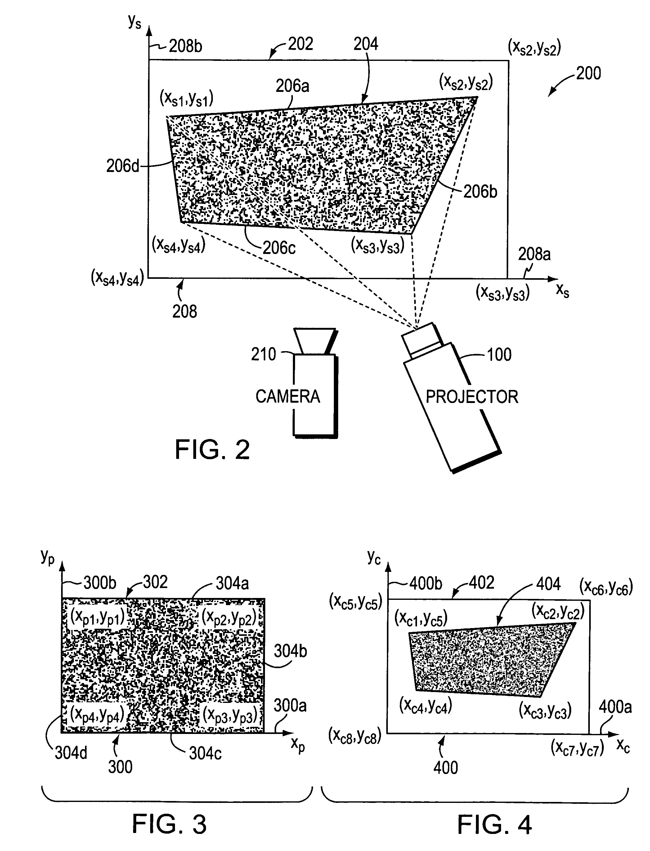
[0025]In order to generate a mapping between the screen coordinate system 208 and the projector coordinate system 300, a camera 210 (FIG. 2) is used to capture and record the geometry of the screen image 204. In the present invention, the camera 210 is positioned such that its optical axis (not shown) is perpendicular to the screen 202 in all planes. As with the screen 202 and the projector 100, a camera coordinate system is also generated, at least logically.

[0026]FIG. 4 is a highly schematic illustration of a camera coordinate system 400 that includes an x-axis, xc, 400a and a y-axis, yc, 400b. Defined within the camera coordinate system 400 is an image of the screen 402 as captured by the camera 210. Within the camera-screen image 402 is a camera-projection image 404 of the screen image 204 (FIG. 2) generated by the projector 100. Because the camera 210 has been positioned such that its optical axis is perpendicular to the screen 202 in all planes, the screen and camera coordinat...

second embodiment

[0080]FIG. 9 is a highly schematic illustration of a run-time system 900 in accordance with this second embodiment of the system. Run-time system 900 includes a front end look-up table (LUT) 902 that receives uncorrected input levels from interface 102 (FIG. 1) as indicated by arrow 904. Run-time system 900 further includes a spatial attenuation array 906 that receives the pixel addresses, in projector space, i.e., xp, yp, corresponding to the respective input levels being supplied to the front end LUT 902, as indicated by arrow 908. The run-time system 900 also includes multiplier logic 910 that receives the output of the front end LUT 902 and the spatial attenuation array 906 for each input level / x,y coordinate pair. The multiplier logic 910 multiplies those outputs together and the resulting “corrected” input level is supplied eventually to the light engine 108 along with the corresponding pixel address information, as indicated by arrows 912 and 914, respectively.

[0081]The atten...

third embodiment

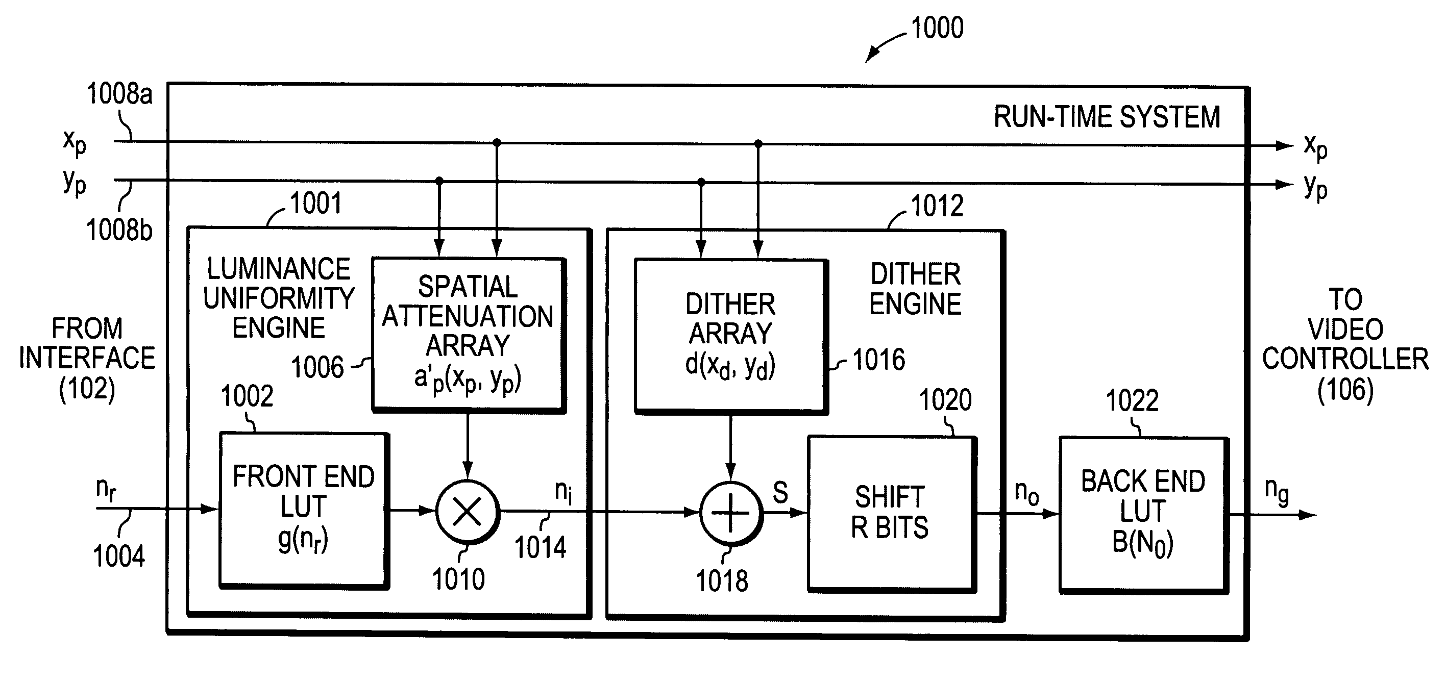
[0083]FIG. 10 is a highly schematic illustration of a run-time system 1000 in accordance with this third embodiment of the system. Run-time system 1000 includes a luminance uniformity engine 1001, a dither engine 1012 and a back-end look-up table 1022 that cooperate to process input image information so that the resulting image generated by projector 100 (FIG. 1) is uniform in luminance and appears to have been produced from a greater number of levels than the number of unique levels that the projector 100 is capable of producing. The luminance uniformity engine 1001 includes a front end look-up table (LUT) 1002 that receives an uncorrected, raw input level, nr, from interface 102, as indicated by arrow 1004, and a spatial attenuation array 1006 that receives the pixel addresses, in projector space, i.e., xp, yp, as indicated by arrows 1008a–b, corresponding to the respective raw, input level nr, received at the front end LUT 1002. Luminance uniformity engine 1001 further includes m...


PUM


Abstract

A system and method corrects luminance non-uniformity caused by images being obliquely projected onto a screen. A camera is used to record the geometry of the obliquely displayed image. Utilizing this recorded geometry, a homography is then derived that maps pixels between the projector's coordinate system and the screen's coordinate system. Utilizing the homography, the projector pixel that attends to the largest projected area on the screen is identified. Next, the ratio of each pixel's projected area to the largest projected area is computed. These ratios are then organized into an attenuation array that is used to produce “corrected” luminance information from input image data. The projector is then driven with the “corrected” luminance information.

Description

BACKGROUND OF THE INVENTION[0001]1. Field of the Invention[0002]The present invention relates to electronic imaging systems and, more specifically, to correcting projected or displayed images.[0003]2. Background Information[0004]There are a wide-variety of digital image projectors that are currently available. Most digital projectors include a video decoder and a light engine. The video decoder converts video data received by the projector, e.g., from the display connection of a personal computer (PC), into pixel and color data. The pixel and color data is then supplied to the light engine, which converts that data into the actual projected image. The light engine includes a lamp, optics and logic for manipulating the light in order to generate the pixels and color.[0005]There are three different types of technologies utilized by the light engines of today's projectors: Liquid Crystal Display (LCD), Digital Light Processing (DLP) and Liquid Crystal on Silicon (LCOS). An LCD light en...

Claims


Application Information

Patent Timeline
Patent Type & Authority Patents(United States)
IPC IPC(8): G03B21/00G03B21/14G06K15/00G09G5/02H04N5/64G03B21/26
CPCG03B21/26H04N9/3182H04N9/3197H04N9/3194H04N9/3185
Inventor ULICHNEY, ROBERT ALANSUKTHANKAR, RAHUL
Owner HEWLETT PACKARD DEV CO LP
Why Eureka
Try Eureka