
Variable displacement pump and control therefore for supplying lubricant to an engine

Active Publication Date: 2006-03-28
SLW AUTOMOTIVE +1
View PDF138 Cites 52 Cited by
  • Summary
  • Abstract
  • Description
  • Claims
  • Application Information

AI Technical Summary

Benefits of technology

[0005]A control system for a hydraulic variable displacement vane-type pump wherein input from an engine control un

Problems solved by technology

First, there is not much control of the actual discharge pressure relative to the pressure needed by the engine under certain / given operating conditions.
At crucial start-up, this cannot be facilitated with the direct drive pumps.
This results in inefficient use of engine power and / or inefficient engine oil lubrication.

Method used


Image

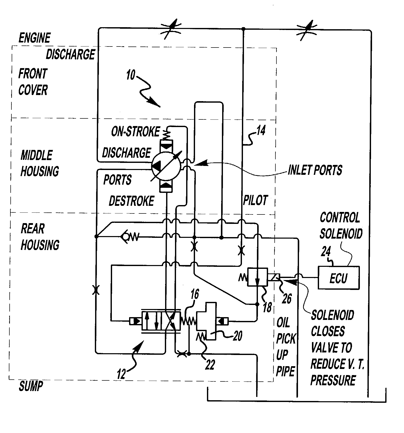
  • Variable displacement pump and control therefore for supplying lubricant to an engine
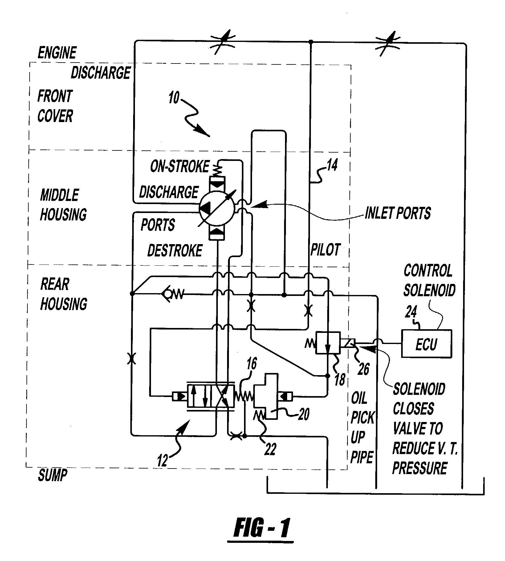
  • Variable displacement pump and control therefore for supplying lubricant to an engine
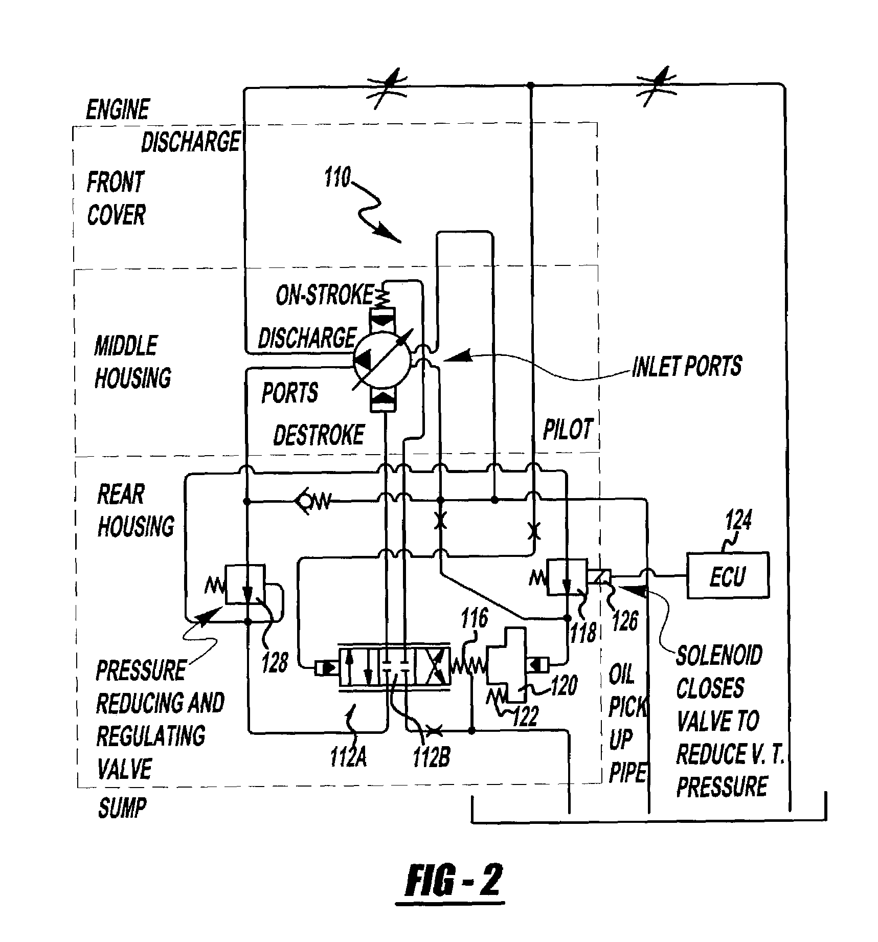
  • Variable displacement pump and control therefore for supplying lubricant to an engine

Examples


Embodiment Construction

[0017]The following description of the preferred embodiment(s) is merely exemplary in nature and is in no way intended to limit the invention, its application, or uses.

[0018]In the present invention, a method of controlling a variable displacement pump 10 for an engine is provided. In a preferred embodiment of the invention that incorporates a solenoid 26, unless stated otherwise, it should be understood that the solenoid 26 is normally, or is defaulted to, the closed position when no power is supplied to the solenoid 26. When the solenoid 26 is in the closed position there will be high fluid displacement by the pump 10. Thus, in an emergency event, such as when there is an electrical failure, the solenoid 26 will move to its default position so the engine oil pressure will remain high and that the vehicle can continue operating until it can serviced. However, it is to be understood that with the solenoid in a closed position the system could also be configured so that there is flui...


PUM


Abstract

A control system for a variable displacement pump. The control system is operably associated with an engine control unit for passively or actively controlling the output of the pump in response to signals from the engine control unit.

Description

CROSS-REFERENCE TO RELATED APPLICATIONS[0001]This application is a non-provisional application basing priority on U.S. Provisional Application No. 60 / 369,829, filed Apr. 3, 2002.FIELD OF THE INVENTION[0002]The present invention relates to the control of the output of a variable displacement pump. More specifically, the present invention relates to control of an oil pump for oil pressure control in an internal combustion engine, transmission or the like.BACKGROUND OF THE INVENTION[0003]It is desirable to properly lubricate the moving components in an internal combustion engine and provide hydraulic power. Typically, oil pumps used in engines are directly connected to the crankshaft of the engine. While this configuration is generally adequate, there are some disadvantages. First, there is not much control of the actual discharge pressure relative to the pressure needed by the engine under certain / given operating conditions. For instance, during start-up conditions it may be desirable...

Claims


Application Information

Patent Timeline
IPC IPC(8): F04B1/06F01M1/16F04C14/24F04B49/00F04B49/06F04C14/22
CPCF01M1/16F04C14/22F04C2270/18F04C2270/052F04C2270/01
Inventor HUNTER, DOUGLASKOENIG, DENNIS
Owner SLW AUTOMOTIVE
Learn More