Shielded electrical connector

a technology of shielded electrical connectors and electrical connectors, which is applied in the direction of coupling device connections, coupling protective earth/shielding arrangements, electrical apparatus, etc., can solve the problems of increasing data rates between circuit boards and cables, creating challenges with respect to “noise” and interference between devices, and significantly increasing the size of electrical connectors

Inactive Publication Date: 2006-03-28
MOLEX INC
View PDF25 Cites 26 Cited by
  • Summary
  • Abstract
  • Description
  • Claims
  • Application Information

AI Technical Summary

Benefits of technology

[0011]According to one aspect of the invention, the board-engaging pads are configured for surface engaging the printed circuit board. In addition, the terminals include portions adapted for surface connection to appropriate circuit means on the printed circuit board. Although the invention is not limited to such configurations, this avoids having to drill large holes in the printed circuit board.

Problems solved by technology

In many applications, the challenge is to increase data rates between circuit boards and cables.
This, in turn, creates challenges with respect to “noise” and interference between the devices.
Of course, this approach significantly increases the sizes of the electrical connectors in high speed applications where miniaturization is a constant goal.

Method used


Image

  • Shielded electrical connector
  • Shielded electrical connector
  • Shielded electrical connector

Examples


Embodiment Construction

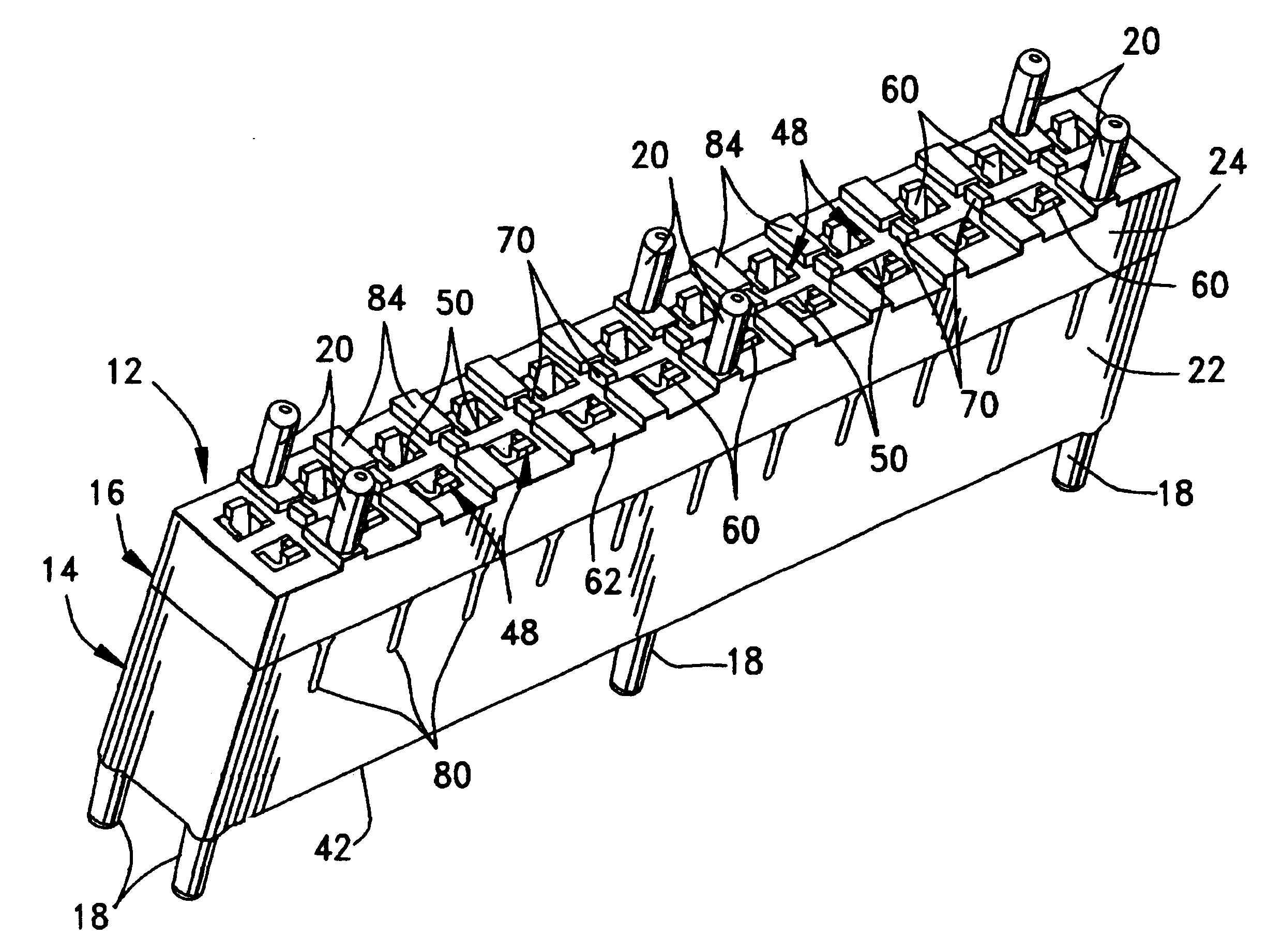
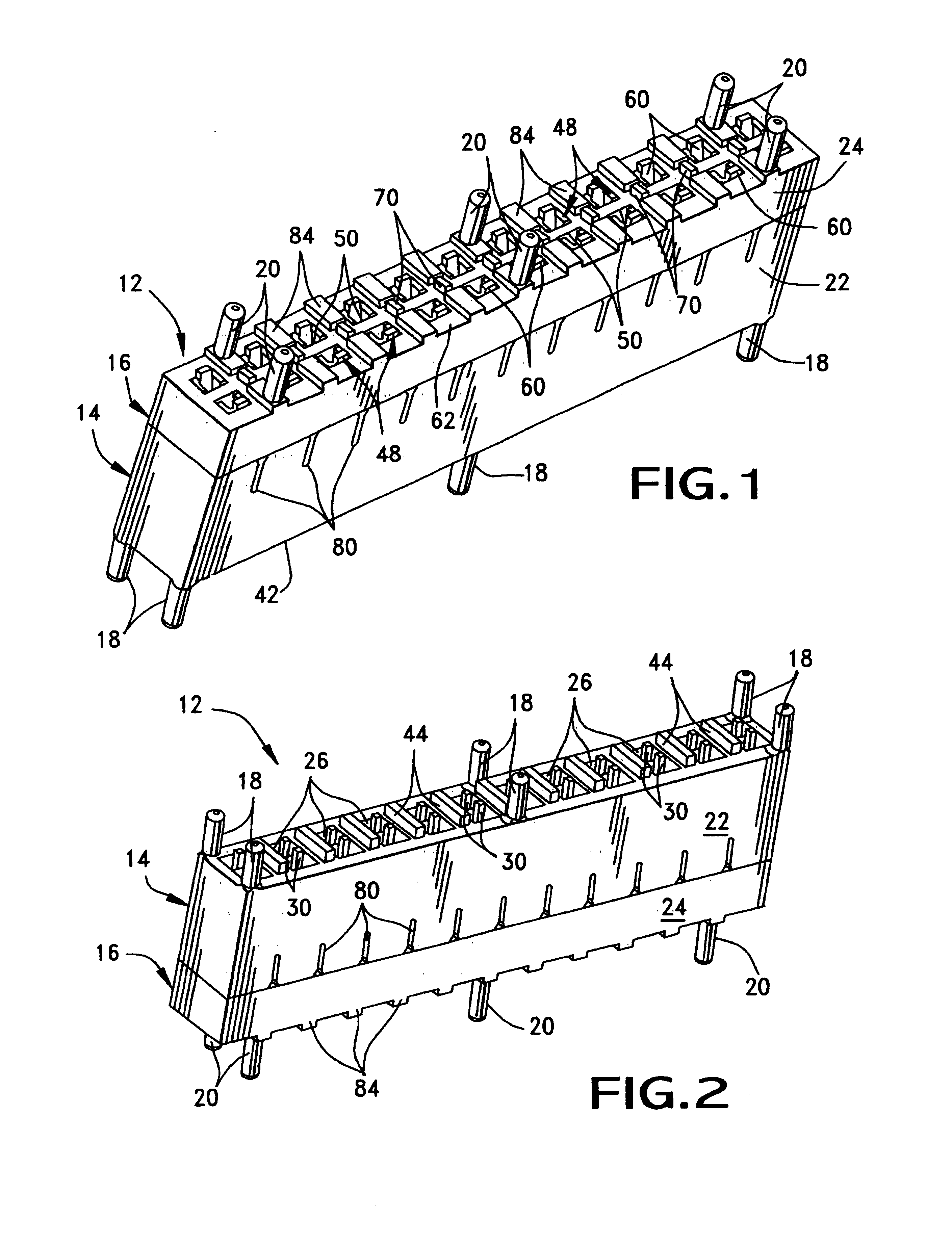
[0039]Referring to the drawings in greater detail, FIGS. 1-9 show a first embodiment of a connector assembly incorporating the concepts of the invention, and FIGS. 10-21 show a second embodiment of a connector assembly also incorporating the concepts of the invention. Referring to the first embodiment of FIGS. 1-9, and first to FIGS. 1 and 2, the invention is incorporated in an electrical connector assembly, generally designated 12, which includes a first or primary connector, generally designated 14, and a second or mating connector, generally designated 16. The connector assembly is a “mezzanine” connector assembly in that it is provided for electrically interconnecting two parallel printed circuit boards. To that end, it can be seen that primary connector 14 includes a plurality of mounting posts 18 for insertion into appropriate mounting holes in a first printed circuit board (not shown) which may be a main or motherboard. Mating connector 16 includes a plurality of mounting pos...


PUM


Abstract

A shielded electrical connector is provided for mounting on a printed circuit board. The connector includes a dielectric housing having a plurality of terminal-receiving cavities and a plurality of board-engaging pads projecting from the bottom of the housing. A plurality of terminals are received in the cavities. Portions of the housing between the terminals are plated with conductive metal material to electrically shield the terminals from each other and to provide a controlled impedance. The plating is continuous onto the pads for connection to appropriate ground circuit means on the printed circuit board. In an alternative embodiment, a shielded electrical connector assembly includes a pair of connectors both of which have plated housings with interengaging plated portions.

Description

FIELD OF THE INVENTION[0001]This invention generally relates to the art of electrical connectors and, particularly, to shielded electrical connectors which are particularly useful for mounting on printed circuit boards and for interconnecting parallel printed circuit boards.BACKGROUND OF THE INVENTION[0002]Dramatic changes are occurring in the wireless, switching and networking industries which are creating a need to transmit information at an ever-increasing rate. For instance, Internet content is expected to be received by cell phones, notebook computers and the like without the need for wires and with considerable speed. In many applications, the challenge is to increase data rates between circuit boards and cables. As the speed and frequency of these devices increase, all of the components within a system must be capable of performing at those speeds. This, in turn, creates challenges with respect to “noise” and interference between the devices. Therefore, it is necessary to iso...

Claims


Application Information

Patent Timeline
Patent Type & Authority Patents(United States)
IPC IPC(8): H01R13/648H01R13/658
CPCH01R13/65807H01R13/6599H01R13/6594H01R13/6585Y10S439/931
Inventor ZADEREJ, VICTORREGNIER, KENT E.DUNHAM, DAVID E.ALBERTS, KEVINBREARLEY, JR., DAVID
Owner MOLEX INC
Why Eureka
Try Eureka