
Methods and circuits for programmable current limit protection

a technology of programmable current and limit protection, applied in the direction of power conversion systems, instruments, process and machine control, etc., can solve the problems of excessive current flow, delay in reducing the initial duty cycle, and potential damage to those components or loads

Active Publication Date: 2006-03-28
ANALOG DEVICES INT UNLTD
View PDF91 Cites 98 Cited by
  • Summary
  • Abstract
  • Description
  • Claims
  • Application Information

AI Technical Summary

Benefits of technology

[0014]In view of the foregoing, it is an object of the present invention to provide methods and circuits for protecting power converters from over-current conditions by providing both steady-state and cycle-by-cycle current limit protection.
[0015]It also is an object of the present invention to provide methods and circuits for protecting power converters from over-current conditions, in which current limit thresholds are user-programmable.
[0016]It further is an object of the present invention to provide methods and circuits for protecting power converters from over-current conditions, in which a signal indicative of inductor current flowing through the power converter is obtained without increasing output current, and thereby exacerbating the over-current condition.

Problems solved by technology

One fault condition that a regulator may experience is an over-current condition at the regulator output, where the current demanded by the load is significantly greater than the nominal maximum output current of the regulator.
The over-current condition may cause excessive currents to flow through the components of the regulator and to be delivered at the regulator's output, causing potential damage to those components or the load, particularly when the over-current condition remains at the regulator output for a prolonged period of time.
One of the problems with this approach is that there may be a delay in reducing the initial duty cycle to the lower duty cycle.
During the transient phase when the duty cycle is being reduced, the inductor current is unregulated and may cause excessive currents to flow, limited only by the normally small input source, MOSFET and inductor impedances.
This scheme, however, also has drawbacks because the top MOSFET must be turned ON to sense the current flowing through the inductor—a situation that is undesirable during an over-current condition—and thus requires an additional fault counter and restart scheme to keep the inductor current from running away, all without ever achieving steady-state regulation of the output current (i.e., regulation of the average value of the output current).

Method used


Image

  • Methods and circuits for programmable current limit protection
  • Methods and circuits for programmable current limit protection
  • Methods and circuits for programmable current limit protection

Examples


Embodiment Construction

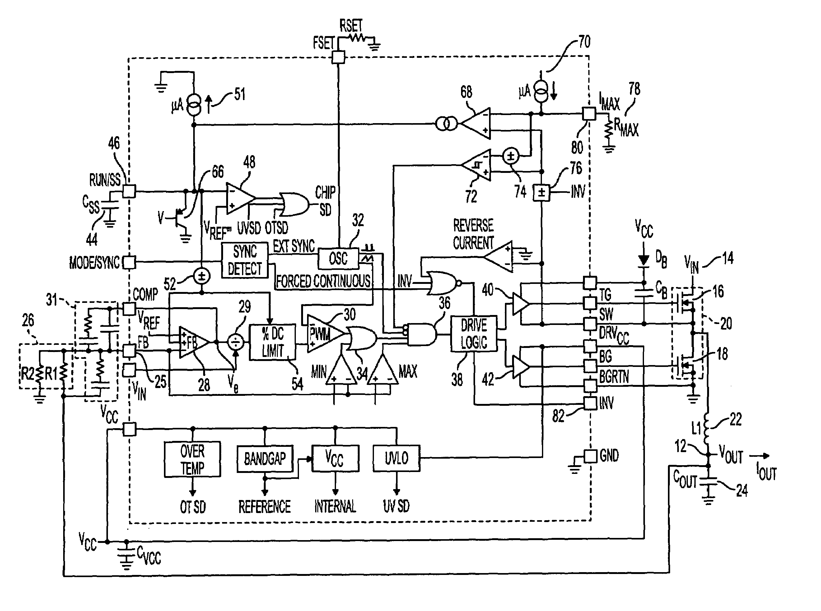
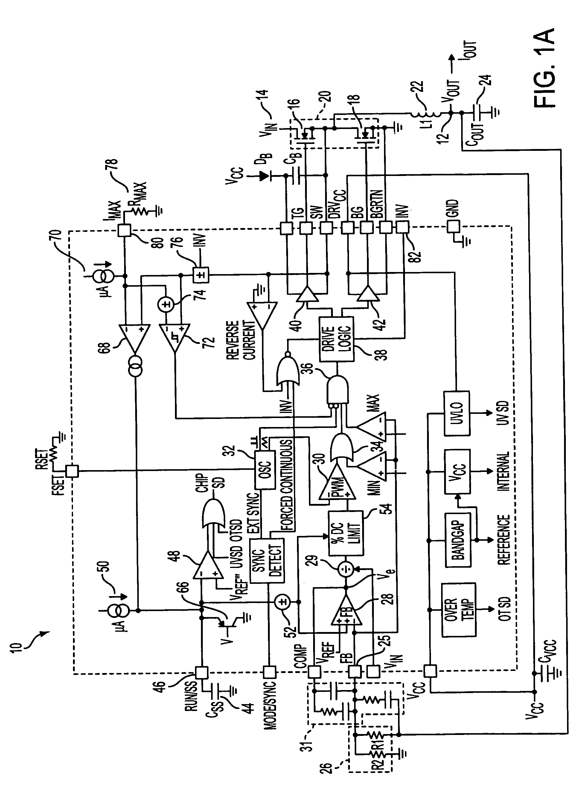
[0033]Referring to FIG. 1A, an illustrative synchronous voltage regulator that operates in either buck or boost mode is described, the voltage regulator incorporating an embodiment of the current limit protection circuit of the present invention. Operation of voltage regulator 10 in buck mode is described first.

[0034]Voltage regulator 10 operates from a supply voltage VIN, e.g., a battery, coupled to input terminal 14, and may be used to provide an output current at an output voltage VOUT within a desired range of a nominal regulated value at output terminal 12 for driving a load (not shown), e.g., a portable laptop computer or other battery-operated system, that is coupled to the output terminal. Output voltage VOUT is maintained at a regulated level by continuously and synchronously switching top-side MOSFET 16 and bottom-side MOSFET 18 of push-pull switch 20. In buck mode, top-side MOSFET 16 serves as the switch element that conducts inductor current when that current is ramping ...


PUM


Abstract

The present invention provides methods and circuits for protecting power converters from over-current conditions that, in one embodiment, (1) reduce average inductor current to a steady-state threshold during a transient phase and regulate average inductor current in steady-state regulation approximately at the steady-state threshold; and (2) reduce instantaneous inductor current after the instantaneous inductor current exceeds a maximum instantaneous threshold during the transient phase.

Description

FIELD OF THE INVENTION[0001]The present invention relates to power converter circuits. More particularly, the present invention relates to methods and circuits for power converters having user-programmable current limit protection.BACKGROUND OF THE INVENTION[0002]Voltage regulators, which are a type of power converter, provide an output voltage to a load within a desired range of a nominal regulated value from a voltage source that may be poorly-specified or fluctuating, or that may be at an inappropriate amplitude for the load. Such regulators may employ a switching circuit that includes one or more switching elements coupled in series or in parallel with the load. The switching elements may be, for example, power metal-oxide semiconductor field-effect transistor (MOSFET) switches.[0003]Control circuitry regulates the output voltage and the current supplied to the load by cycling the switch circuit between ON and OFF states. The duty cycle of the switch circuit controls the flow of...

Claims


Application Information

Patent Timeline
IPC IPC(8): G05F1/56
CPCH02M1/32H02M2001/0012H02M1/0012
Inventor DITTMER, GREGORY P.HOUK, TALBOTT M.
Owner ANALOG DEVICES INT UNLTD
Features
  • Generate Ideas
  • Intellectual Property
  • Life Sciences
  • Materials
  • Tech Scout
  • Unparalleled Data Quality
  • Higher Quality Content
  • 60% Fewer Hallucinations
Learn More