
Socket structure

a socket and socket technology, applied in the direction of wheel mounting apparatus, wrenches, vehicle components, etc., can solve the problems of easy scratching of the rim, difficult to be accepted by picky vehicle owners, and high price of aluminum alloy wheels, so as to avoid scratching the rim, the overall stiffness is insufficient, and the effect of easy scratching

Active Publication Date: 2021-10-21
PENG CHIA HUI +4
View PDF0 Cites 0 Cited by
  • Summary
  • Abstract
  • Description
  • Claims
  • Application Information

AI Technical Summary

Benefits of technology

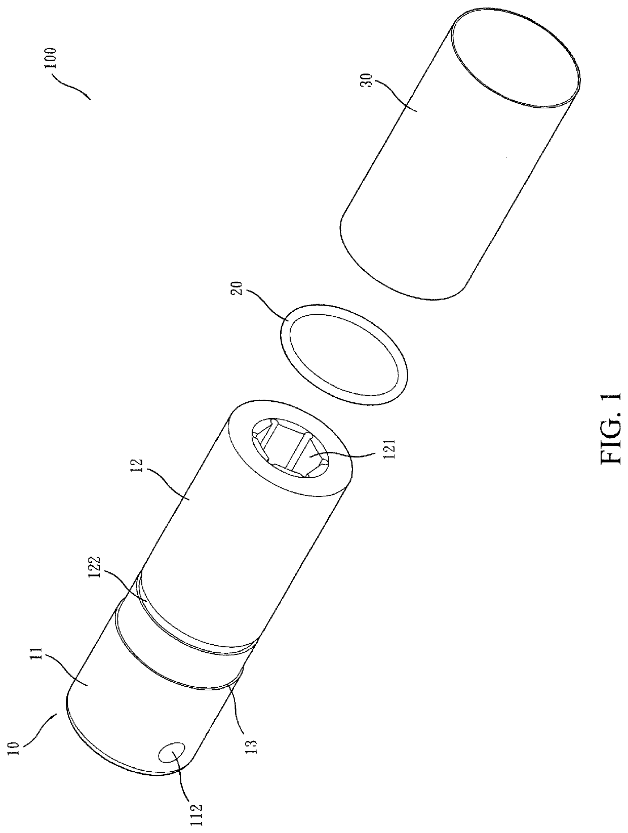
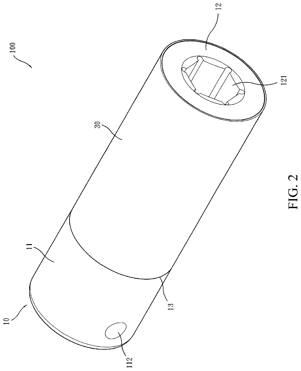
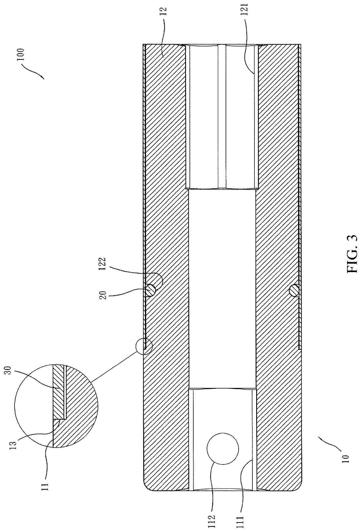
The present invention provides a socket structure that includes a socket body, an O-ring, and a carbon-fiber tube. The socket body has a driving section and an acting section, and the driving section has a step portion with a driving hole. The acting section has a step portion with an acting hole. The O-ring is fit into the circumferential groove of the socket body. The carbon-fiber tube is fit over the outer circumferential surface of the acting section of the socket body and has an end in abutting engagement with the stepped portion and an internal circumferential surface in contact with the O-ring. The invention aims to improve protection and ease of use while being adaptable to an existing wheel rim and ensuring overall stiffness and easy assembly.

Problems solved by technology

When the socket is applied to tighten or loosen nuts or during pre-operations or post-operations thereof, it readily occurs that the socket hits the wheel rim, leading to scratching on the rim.
This may be a situation that is hard to be accepted for a picky vehicle owner or a vehicle owner whose wheel rim (such as an aluminum alloy rim) is highly expensive.
This is tedious in operation and often makes it hard to fit the socket into openings in the wheel rim, making it generally inoperable.
However, a plastic casing that is too thin may not provide a proper effect of protection; and a plastic casing that is too thick prevents the extension of the socket into the openings in the wheel rim.
Further, this may require reduction of the outside diameter of the socket, leading to lowering of overall stiffness.
In addition, combining the plastic casing to the socket is generally done with a relatively tight surface contact therebetween and this makes parts assembling difficult.

Method used


Image

  • Socket structure
  • Socket structure
  • Socket structure

Examples


Embodiment Construction

[0009]For better understanding and recognition of the features and advantages of the present invention, a detailed description will be given below to an embodiment of the present invention, with reference being had to the attached drawings:

[0010]Referring to FIGS. 1-3, a socket structure provided according to a preferred embodiment of the present invention is generally designated at 100 and generally comprises a socket body 10, an O-ring 20, and a carbon-fiber tube 30.

[0011]Referring to FIGS. 1-3, the socket body 10 is a one-piece, integrally formed cylindrical barrel. The socket body 10 includes a driving section 11 and an acting section 12 integrally and coaxially connected with the driving section 11. The driving section 11 has an outside diameter that is greater than an outside diameter of the acting section 12 so that a stepped portion 13 is formed at the connection between the driving section 11 and the acting section 12 as extending along outer circumferential surfaces of the...


PUM


Abstract

A socket structure includes a socket body, an O-ring, and a carbon-fiber tube. The socket body includes a driving section and an acting section coaxially connected to the driving section. The driving section has an outside diameter greater than an outside diameter of the acting section and a stepped portion is formed in outer circumference between the driving section and the acting section. The driving section and the acting section have end faces that are recessed inwardly to form a driving hole and an acting hole, respectively. The outer circumferential surface of the acting section is formed with a circumferential groove in which the O-ring is received. The carbon-fiber tube is fit over the outer circumferential surface of the acting section of the socket body and has an end in abutting engagement with the stepped portion and an internal circumferential surface in contact with the O-ring.

Description

TECHNICAL FIELD OF THE INVENTION[0001]The present invention relates generally to an accessory of pneumatic tools, and more particularly to a structure of a socket.DESCRIPTION OF THE PRIOR ART[0002]A pneumatic tool is commonly used as a power source to for example mount a wheel rim to an automobile or to remove a wheel rim from an automobile so that through proper attachment to a socket, the tool can be operated to tighten or loosen nuts.[0003]However, the socket that attaches to the pneumatic tool must be of certain level of stiffness in order to avoid undesired deformation, and is thus commonly made of metals. When the socket is applied to tighten or loosen nuts or during pre-operations or post-operations thereof, it readily occurs that the socket hits the wheel rim, leading to scratching on the rim. This may be a situation that is hard to be accepted for a picky vehicle owner or a vehicle owner whose wheel rim (such as an aluminum alloy rim) is highly expensive. Consequential disp...

Claims


Application Information

Patent Timeline
Patent Type & Authority Applications(United States)
IPC IPC(8): B60B29/00
CPCB60B29/003B60B29/006B25B13/06
Inventor PENG, CHIA-HUI
Owner PENG CHIA HUI
Learn More