Electric conductivity water probe

a water probe and conductivity technology, applied in the direction of transportation and packaging, instruments, separation processes, etc., can solve the problems of aircraft fuel pumped through the water separator vessel, excessive amount of water to the water separating vessel, and inability to further separate water from fuel,

Active Publication Date: 2006-03-28
CROWN PRODS
View PDF18 Cites 119 Cited by
  • Summary
  • Abstract
  • Description
  • Claims
  • Application Information

AI Technical Summary

Benefits of technology

[0018]Periodic actuation of the instant invention's ability to “mimic” a high water event provides protections against undesirable high water detection failures as described above without requiring flooding of the water separating vessel with water. In order to cause the instant inventive electric conductivity water probe to mimic a high water event, the first valve means is actuated to close the fluids input / output port. Thereafter, fuel contained within the test chamber is purged, preferably by opening and reclosing a valve controlled fluids output port. Thereafter, the water input port is opened, and water is poured therethrough, filling the test chamber with electrically conductive water. In the event such water completes an electric circuit between the first and at least second wall sections of the test chamber, an operator may accurately infer that electric contact surfaces within such chamber have not been undesirably coated by any contaminants, and the operator may infer that the probe is properly functioning. Thereafter, the water may be purged through the fluids output port, and both the water input port and the fluids output port are thereafter closed. Thereafter, the fluids input / output port is reopened, restoring the test probe to normal water level testing function.

Problems solved by technology

However, on occasion, an excessive amount of water may be present within a fuel truck's tank, resulting in transmission of an excessive amounts of water to the water separating vessel.
In the event water within the sump of such water separating vessel rises to a level at which portions of the vessel's coalescing and separating elements are submerged in water, the vessel's ability to further separate water from fuel may become compromised.
Such a malfunction of the water separator potentially allows water laden fuel to be pumped into an aircraft's fuel tanks.
In-flight aircraft engine failure and a catastrophic crash can result when the engine ingests water contaminated fuel.
However, aircraft fuel pumped through the water separator vessel may, on occasion, be further contaminated (over and above water contamination) by electrically insulating substances which tend to coat the electrode, acting as an electrical insulator.
Where such electrode coating contaminants are present, excess water within the water separating vessel will not necessarily complete an electric circuit within the water probe.
In such event, the aforementioned exemplary pump motor kill switch may not be actuated in response to an excess water event, and water laden fuel may be undesirably pumped downstream and into an aircraft's fuel tank.
However, such measures are mechanically complex and time consuming, resulting in an undesirable aircraft refueling system down time.
However, such protective procedures similarly are time consuming, and undesirably result in aircraft fueling system down time.

Method used


Image

  • Electric conductivity water probe
  • Electric conductivity water probe
  • Electric conductivity water probe

Examples


Embodiment Construction

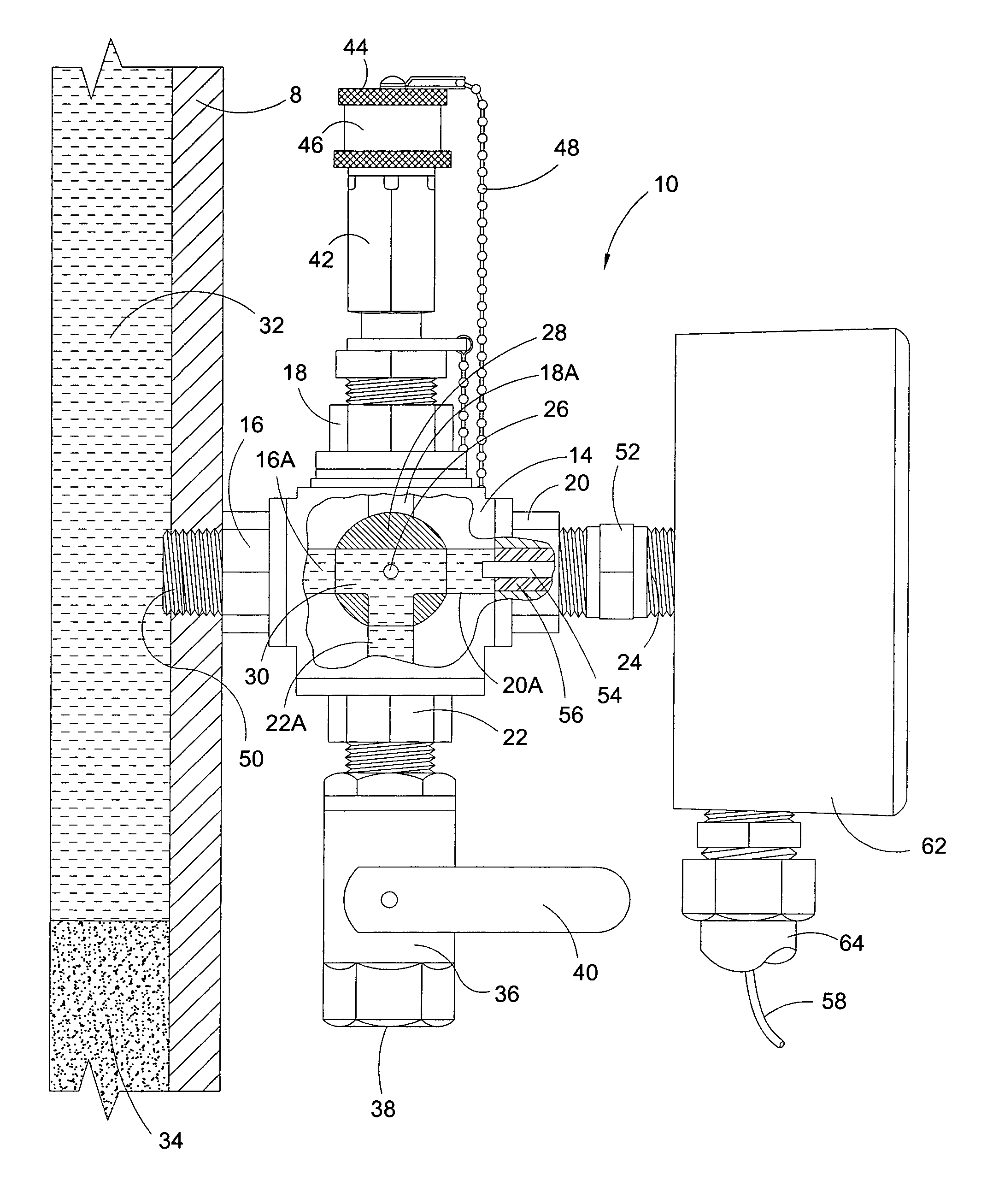
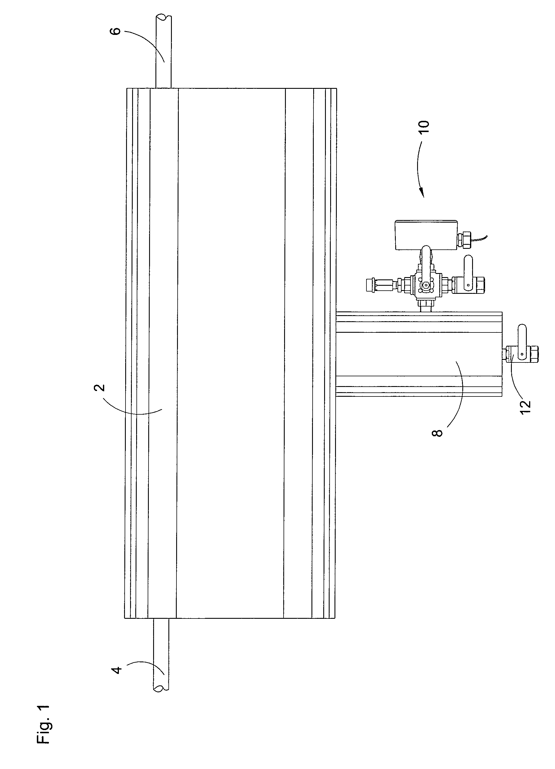
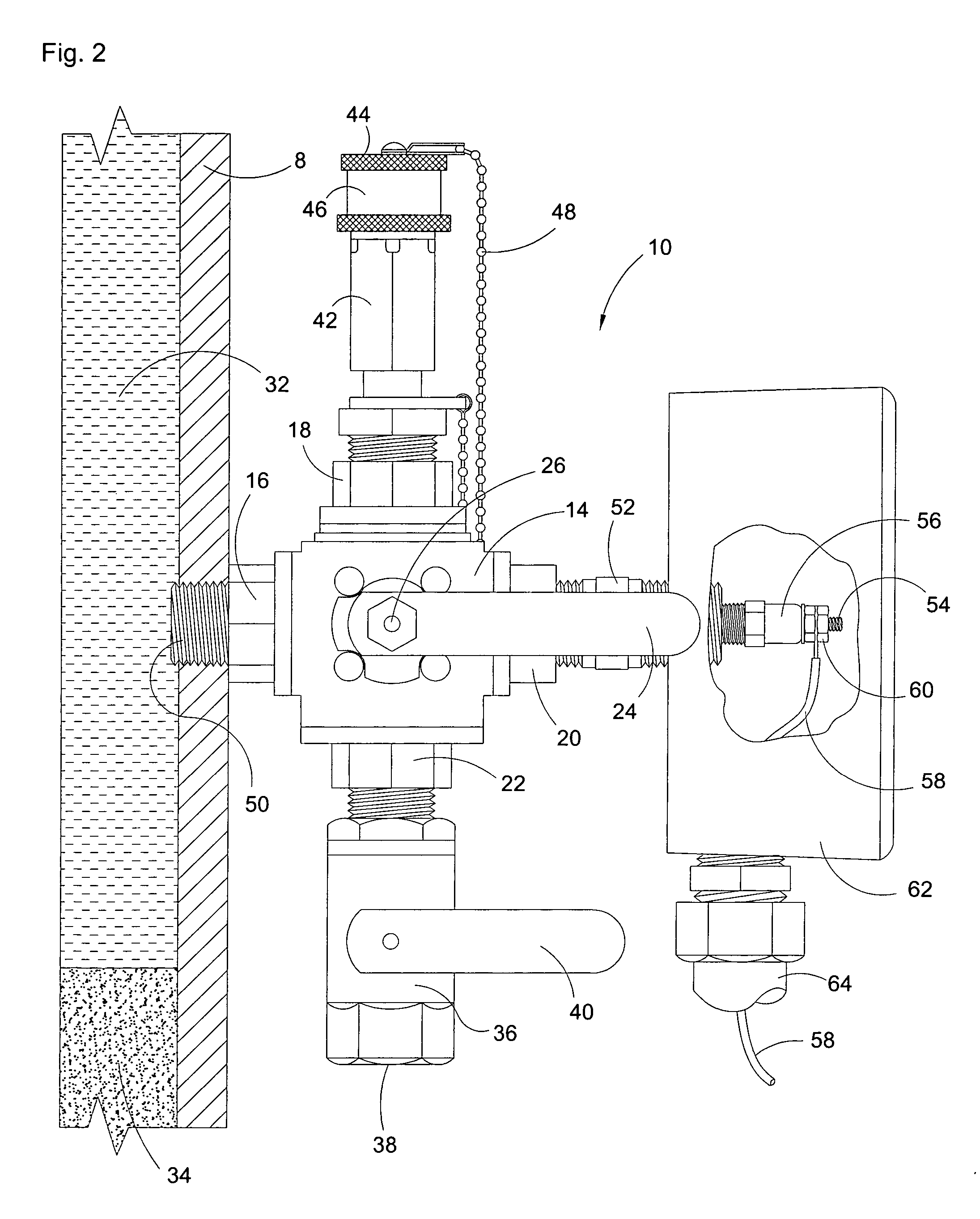
[0026]Referring now to the drawings, and in particular to FIG. 1, the instant inventive electric conductivity water probe is referred to generally by Reference Arrow 10. The electric conductivity water probe 10 is shown attached to a water collecting sump 8, such sump being attached at a low end of, for example, an aircraft fuel water separating vessel 2. Aircraft fuel may be pumped from a fuel truck (not depicted) through fuel line 4 and into separating vessel 2. Thereafter, water coalescing and water separating elements (not depicted) encased within vessel 2 separate water from the fuel. De-watered fuel emits from fuel line 6 for transmission to, for example, an aircraft's fuel tank (not depicted). Water separated within vessel 2 flows downwardly into water collecting sump 8. Under normal circumstances, such collected water does not rise within sump 8 above the level of probe 10. After each fueling operation, water purge valve 12 may be opened, allowing collected water from to dra...


PUM

PropertyMeasurementUnit
electric conductivityaaaaaaaaaa
insulatingaaaaaaaaaa
volatileaaaaaaaaaa

Abstract

An electric conductivity water probe consisting of a test chamber having a wall, a fluids input / output port, and a water input port, the wall having a first and at least a second wall section, the first and at least second wall sections being electrically isolated from each other by an electrical insulator; and a valve connected operatively to the fluids input / output port, the valve being adapted for alternately and permitting and resisting flows of fluids through the fluids port.

Description

FIELD OF THE INVENTION[0001]The invention described hereinbelow relates to volatile fluids transport and storage systems. More particularly, said invention relates to such systems which incorporate structure adapted for separation of water from the volatile fluids, and which are adapted for collection of such water at a water collection point, said invention further relating to apparatus applicable to such water collection point and which are adapted for probing or testing for excessive water accumulations.BACKGROUND OF THE INVENTION[0002]An environment in which the instant inventive electric conductivity water probe may be advantageously used is an airport aircraft maintenance tarmac. In such environment, a fuel truck having a tank for transporting aircraft fuel commonly services aircrafts by pumping fuel into an aircraft's fuel tanks. Water, which upon occasion undesirably collects within and contaminates the tank of such a fuel truck, is necessarily prevented from being pumped in...

Claims


Application Information

Patent Timeline
Patent Type & Authority Patents(United States)
IPC IPC(8): G01R27/08G01N27/06G01N33/18
CPCG01N33/1886G01N27/06Y10T137/3006Y10T137/86871
Inventor KITTRELL, MICHAEL E.
Owner CROWN PRODS
Why Eureka
Try Eureka