Line driver with active termination

a technology of active termination and line driver, which is applied in the direction of pulse generator, pulse technique, picture signal generator, etc., can solve the problems of complex circuit design of non-inverting type amplifier, and achieve the effect of reducing the voltage amplitude of a signal

Active Publication Date: 2006-03-28
REALTEK SEMICON CORP
View PDF10 Cites 7 Cited by
  • Summary
  • Abstract
  • Description
  • Claims
  • Application Information

AI Technical Summary

Benefits of technology

[0007]The object of the present invention is to provide a line driver with active term

Problems solved by technology

Thus, the circuit design of the non-in

Method used


Image

  • Line driver with active termination
  • Line driver with active termination
  • Line driver with active termination

Examples


Embodiment Construction

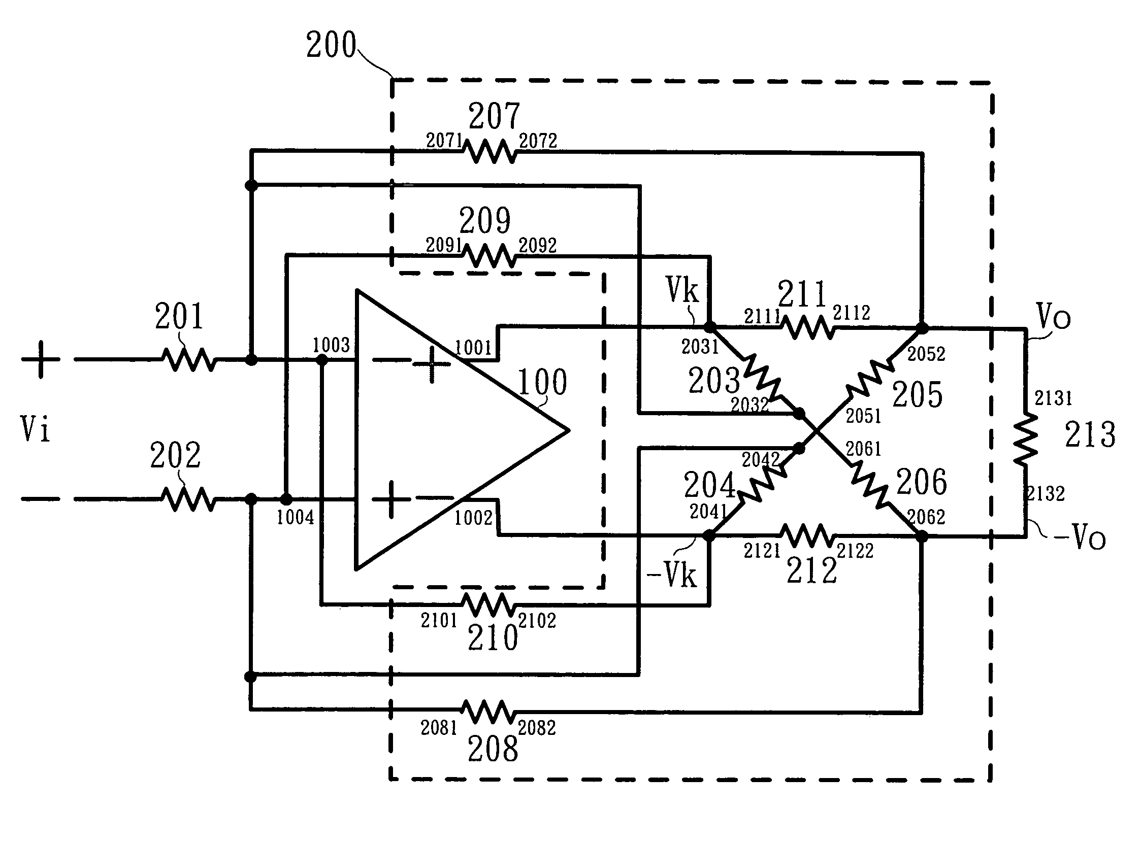
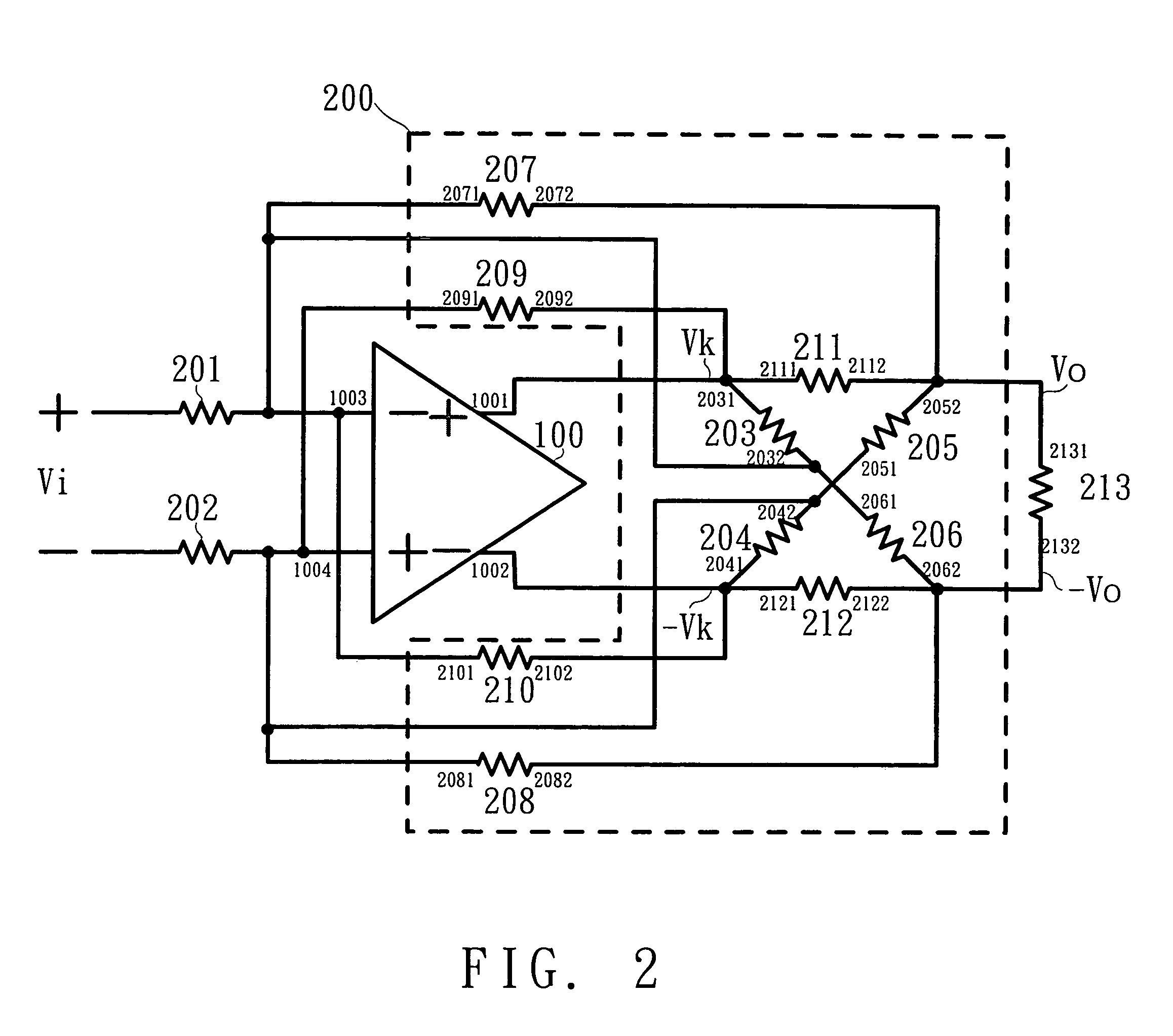
[0017]FIG. 2 shows a line driver according to the first embodiment of the present invention. In FIG. 2, the line driver includes a differential amplifier 100, a first resistor 201, a second resistor 202 and a resistive feedback network 200. The differential amplifier 100 has a non-inverting output terminal 1001, an inverting output terminal 1002, an inverting input terminal 1003, and a non-inverting input terminal 1004. The first resistor 201 and the second resistor 202 are coupled to the inverting input terminal 1003 and a non-inverting input terminal 1004, respectively.

[0018]The resistive feedback network 200 has a plurality of resistors in symmetric configuration. The resistive feedback network 200 is coupled to the non-inverting output terminal 1001, the inverting output terminals 1002, the inverting input terminal 1003, and the non-inverting input terminal 1004 to form a feedback network. The output impedance of the line driver is determined by the resistive feedback network 20...


PUM


Abstract

The line driver with active termination includes: a differential amplifier having an inverting output terminal, a non-inverting output terminal, an inverting input terminal, and a non-inverting input terminal; a first resistor unit coupled to the inverting input terminal; a impedance matching resistor unit coupled to the non-inverting output terminal; and a resistive feedback network, having a plurality of resistors in symmetric configuration. The resistive feedback network further includes: a second resistor unit coupled to the impedance matching resistor unit and the inverting input terminal; a third resistor unit coupled to the non-inverting output terminal and the inverting input terminal; a fourth resistor unit coupled to the impedance matching resistor unit and the inverting input terminal; and a fifth resistor unit coupled to the inverting output terminal and the inverting input terminal. Each of the resistor units and the impedance matching resistor unit includes a plurality of resistors in symmetric configuration.

Description

BACKGROUND OF THE INVENTION[0001]1. Field of the Invention[0002]The present invention relates to a technical field of a line driver and, more particularly, to a line driver with active termination.[0003]2. Description of Related Art[0004]In wired communication systems, a transmission line is commonly used to transmit signals while a line driver is used to drive the transmission line. The typical line driver can be either a voltage mode driver or a current mode driver. FIG. 1A shows a conventional voltage mode line driver. In order to reduce the reflection and energy loss of a transmitting signal, a resistor Rs is required to provide the impedance matching. When Rs=RL, the reflecting signal is minimum and the power transfer is maximum. The magnitude of the signal outputted from the voltage mode line driver 10 has to be double to the signal transmitted on the transmission line because of the impedance matching resistor Rs. Therefore, a voltage source for providing higher voltage power...

Claims


Application Information

Patent Timeline
IPC IPC(8): H03K17/16H03F1/56
CPCH03F1/56
Inventor WANG, WEN-CHILEE, CHAO-CHENGTSAI, JUI-YUAN
Owner REALTEK SEMICON CORP
Why Eureka
Try Eureka