
Thin film magnetic head capable of inhibiting occurrence of track erasing

a thin film, magnetic head technology, applied in the direction of head surfaces, heads with metal sheet cores, instruments, etc., can solve the problems of insufficient measures to inhibit the occurrence of track erasing mainly resulting from the return mechanism of magnetic flux during recording, information cannot be stably recorded on the hard disk, and the reliability of magnetic recording decreases. to achieve the effect of improving the reliability of magnetic recording

Active Publication Date: 2006-03-28
TDK CORPARATION +1
View PDF2 Cites 18 Cited by
  • Summary
  • Abstract
  • Description
  • Claims
  • Application Information

AI Technical Summary

Benefits of technology

The invention provides a thin film magnetic head that can prevent track erasing and improve the reliability of magnetic recording. The head includes a thin film coil, a pole layer, and a return magnetic layer. The return magnetic layer has a width change portion with a width continuously narrowed towards the end surface, which prevents concentration of magnetic flux and prevents damage to the recording medium. The method of manufacturing the thin film magnetic head includes forming a precursor return magnetic layer with a width change portion and polishing it until it reaches a halfway point to form the recording-medium-facing surface. The thin film magnetic head also includes a first shield layer and a second shield layer for magnetically shielding the pole layer and magnetoresistive device, respectively. The pole layer emits magnetic flux in a direction perpendicular to the surface of the recording medium.

Problems solved by technology

When track erasing occurs, information cannot be stably recorded on the hard disk, so the reliability of magnetic recording decreases.
However, in a conventional perpendicular recording system thin film magnetic head, measures to inhibit the occurrence of track erasing mainly resulting from a returning mechanism of the magnetic flux during recording is not sufficient yet.

Method used


Image

  • Thin film magnetic head capable of inhibiting occurrence of track erasing
  • Thin film magnetic head capable of inhibiting occurrence of track erasing
  • Thin film magnetic head capable of inhibiting occurrence of track erasing

Examples


Embodiment Construction

[0036]Preferred embodiments of the invention will be described in more detail below referring to the accompanying drawings.

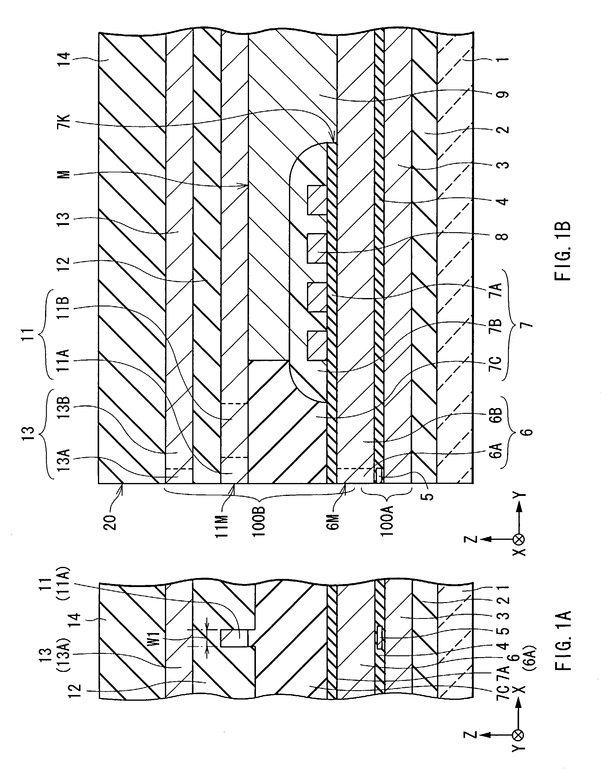
[0037]At first, referring to FIGS. 1A and 1B, the structure of a thin film magnetic head according to an embodiment of the invention will be described below. FIGS. 1A and 1B show sectional views of the thin film magnetic head, and FIG. 1A shows a sectional view parallel to an air bearing surface, and FIG. 1B shows a sectional view perpendicular to the air bearing surface.

[0038]In the following description, a distance in an X-axis direction, a distance in a Y-axis direction and a distance in a Z-axis direction in FIGS. 1A and 1B are expressed as “a width”, “a length” and “a thickness”, respectively. Further a side closer to an air bearing surface in the Y-axis direction is expressed as “front or frontward”, and the opposite side is expressed as “rear or rearward”. In FIGS. 2 through 16, these directions are expressed as the same.

[0039]The thin film magnetic head ...


PUM

PropertyMeasurementUnit
angleaaaaaaaaaa
thicknessaaaaaaaaaa
thicknessaaaaaaaaaa

Abstract

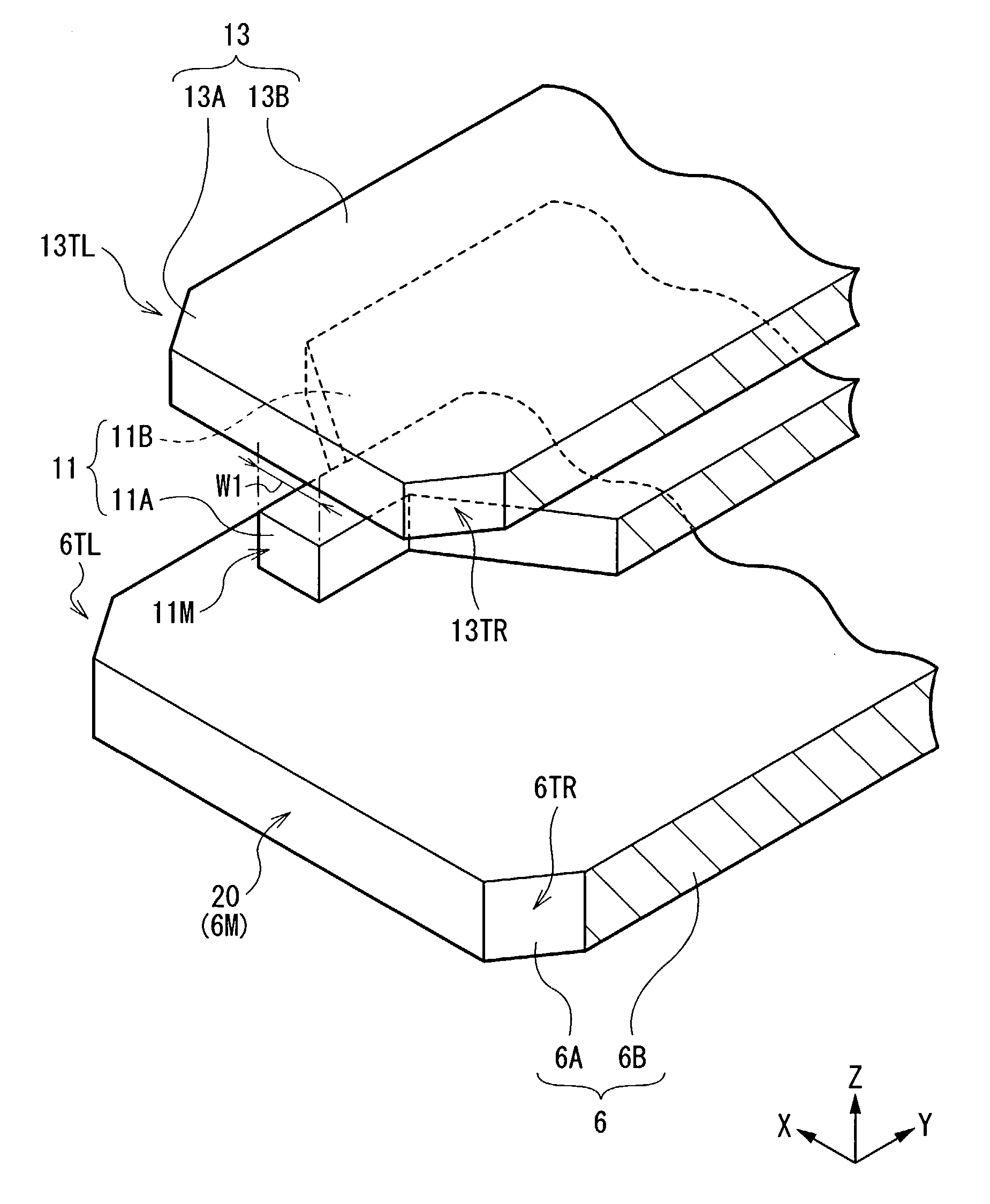
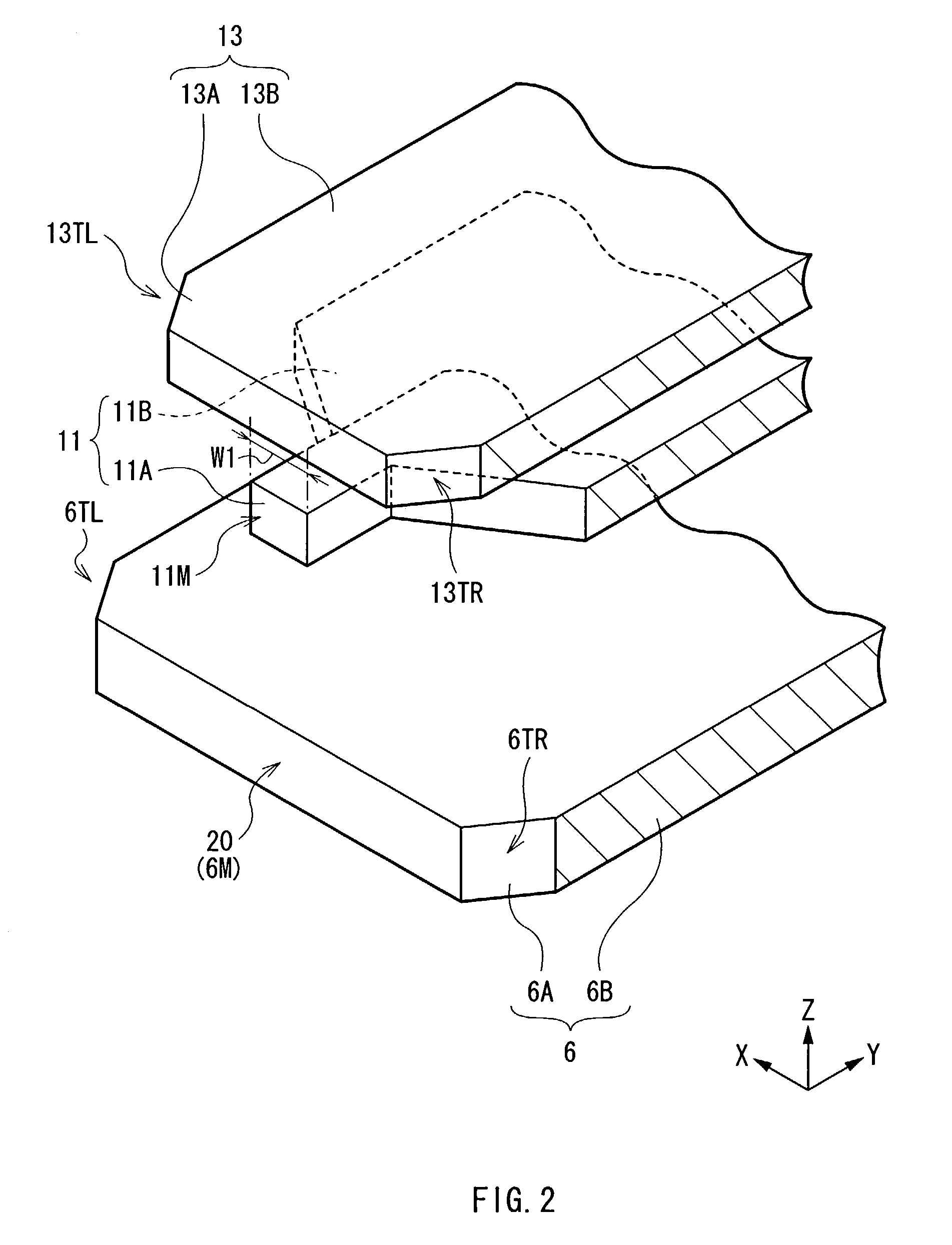
Provided is a thin film magnetic head capable of inhibiting the occurrence of track erasing and improving the reliability of magnetic recording. Two taper surfaces are disposed on both sides of a return yoke layer. As no corner portion which may induce concentration of a magnetic flux exists on the both sides of the return yoke layer, even if the magnetic flux emitted from a pole layer is returned to the return yoke layer through a hard disk, a magnetic field strength is not locally and pronouncedly concentrated in proximity to the taper surfaces of the return yoke layer. Thereby, the concentration of the magnetic flux can be prevented, and the probability of the occurrence of unnecessary recording decreases, so the occurrence of track erasing can be inhibited, and the reliability of magnetic recording can be improved.

Description

BACKGROUND OF THE INVENTION[0001]1. Field of the Invention[0002]The present invention relates to a thin film magnetic head magnetically recording by use of, for example, a perpendicular recording system, and a method of manufacturing the same.[0003]2. Description of the Related Art[0004]In recent years, magnetic recording apparatuses such as, for example, hard disk drives which record information on hard disks have been in widespread use as information recording sources. In the development of hard disk drives, an improvement in performance of thin film magnetic heads has been sought in accordance with an increase in the areal density of the hard disks. As magnetic recording systems applicable to thin film magnetic heads, for example, a longitudinal recording system that a signal magnetic field is oriented in an in-plane direction (a longitudinal direction) of a hard disk and a perpendicular recording system that the signal magnetic field is oriented in a direction perpendicular to a...

Claims


Application Information

Patent Timeline
Patent Type & Authority Patents(United States)
IPC IPC(8): G11B5/147G11B5/00G11B5/127G11B5/187G11B5/31G11B5/39
CPCG11B5/1278G11B5/3116G11B5/313G11B5/1871Y10T29/49043Y10T29/49021Y10T29/49052Y10T29/49048Y10T29/49046G11B2005/0029
Inventor MATONO, NAOTOODA, AKIHIRO
Owner TDK CORPARATION
Learn More