Method for adjusting a phase angle of a phase modifier of a transmitting device

Inactive Publication Date: 2006-03-28
ROHDE & SCHWARZ GMBH & CO KG
View PDF10 Cites 11 Cited by
  • Summary
  • Abstract
  • Description
  • Claims
  • Application Information

AI Technical Summary

Benefits of technology

[0008]The invention is based on the awareness that, by applying an input signal with a predetermined constant inphase component and a predetermined constant quadrature phase component, a deviation of the phase angle can be relatively easily determined. The feedback loop, cons

Problems solved by technology

Of disadvantage in the mode of operation proposed in EP 0 706 259 A1, however, is that the feedback loop for determining the phase angle has to be opened each time.
T

Method used


Image

  • Method for adjusting a phase angle of a phase modifier of a transmitting device
  • Method for adjusting a phase angle of a phase modifier of a transmitting device
  • Method for adjusting a phase angle of a phase modifier of a transmitting device

Examples


Embodiment Construction

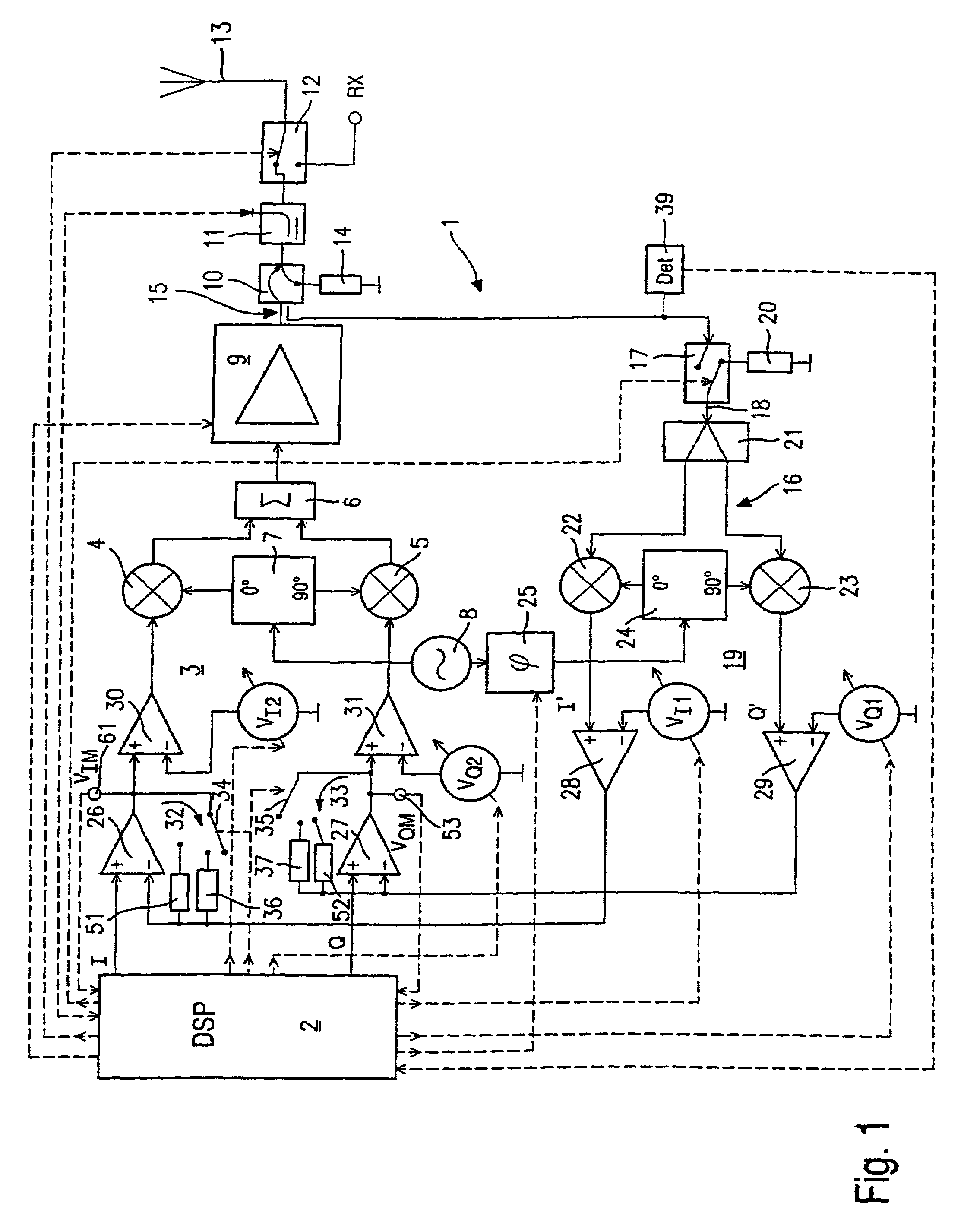
[0018]FIG. 1 shows a transmitting device 1 suitable for carrying out the method according to the invention in a basic block diagram.

[0019]A digital signal processor (DSP) 2 generates a complex input signal for a quadrature modulator 3, consisting of an inphase mixer 4, a quadrature phase mixer 5 and a summer 6, as well as a phase modifier 7. The complex input signal consists of an inphase component I and a quadrature phase component Q, wherein the inphase component I is supplied to the inphase mixer 4 and the quadrature phase component Q is supplied to the quadrature phase mixer 5. The output signal of a local oscillator 8 is supplied to the phase modifier 7, wherein the phase modifier 7 supplies this oscillator signal to the inphase mixer 4 without phase shift and to the quadrature phase mixer 5 at a phase shift of 90°.

[0020]Connected downstream the quadrature modulator 3 is a power amplifier 9 which supplies the quadrature-modulated signal, power-amplified corresponding to the tra...


PUM


Abstract

A method for adjusting a phase angle (φ) of a phase modifier (25) of a transmitting device which includes a quadrature modulator (3), a power amplifier (9), a quadrature demodulator (19) and differential amplifiers (26, 27). The power amplifier (9) is linearized via the feedback loop (16) according to the Cartesian feedback method. The phase modifier (25) supplies an oscillator signal to the quadrature demodulator (19), which signal is shifted by the phase angle (φ) to be adjusted with regard to the oscillator signal that is supplied to the quadrature modulator (3). An input signal with a constant inphase component (I) and a constant quadrature phase component (Q) is applied during each transmission burst in the instance of a closed feedback loop, and the quadrature component (VQM) and/or the inphase component (VIM) is measured at a measuring point (53, 61) located behind the output of the differential amplifiers (26, 27).

Description

[0001]This application is a 371 of PCT / EP00 / 06078, filed Jun. 29, 2000, which claims priority to Germany application No. 199 46 669.6, filed Sep. 29, 1999.BACKGROUND OF THE INVENTION[0002]The invention relates to a method for adjusting a phase angle of a phase modifier of a transmitting device. The transmitting device comprises a quadrature modulator and a power amplifier which is linearized via a so-called Cartesian feedback loop with a quadrature demodulator.[0003]EP 0 706 259 A1 discloses a transmitting device wherein a basic band input signal is supplied to a quadrature modulator via two differential amplifiers. Said quadrature modulator performs quadrature modulation of the inphase component and the quadrature phase component of the complex input signal. Power amplification takes place in a power amplifier connected downstream the quadrature modulator. To compensate the non-linerarity of this power amplifier a feedback loop is provided, generally designated as a Cartesian which...

Claims


Application Information

Patent Timeline
IPC IPC(8): H04L27/20H03F1/32H03F1/34H04L27/36
CPCH03F1/3247H04L27/368H03F1/345
Inventor LIPP, FRIEDRICH
Owner ROHDE & SCHWARZ GMBH & CO KG
Why Eureka
Try Eureka