Wavelength dispersion probing system

a technology of wavelength dispersion and probing system, which is applied in the direction of optical apparatus testing, reflectometers detecting back-scattered light in frequency-domain, instruments, etc., can solve the problems of time, troublesome determination, and unknown signs, and achieve the effect of reducing the time and troublesome determination

Inactive Publication Date: 2006-03-28
ADVANTEST CORP
View PDF10 Cites 111 Cited by
  • Summary
  • Abstract
  • Description
  • Claims
  • Application Information

AI Technical Summary

Benefits of technology

[0005]The present invention is created in view of such points, and aims at providing a wavelength dispersion probing system which can determine the value of wavelength dispersion and its sign and can decrease troubles and time required for the determination.

Problems solved by technology

By the way, since the calculation of wavelength dispersion D using the apparatus disclosed in the gazette mentioned above calculates on the basis of the frequency of intensity amplitude of the detected light, only the absolute value can be found, but there is a problem that a sign is not known.
Since the sign of wavelength dispersion is not found by the method disclosed in the gazette mentioned above, the sign of wavelength dispersion is measured by another method, and hence, there is a problem that determination requires troubles and time since it is necessary to change apparatuses connecting optical fibers or to prepare an apparatus determining the sign of wavelength dispersion in addition to the distributed map.

Method used


Image

  • Wavelength dispersion probing system
  • Wavelength dispersion probing system
  • Wavelength dispersion probing system

Examples


Embodiment Construction

[0018]Hereafter, a wavelength dispersion probing system where the present invention is applied will be described with referring to drawings.

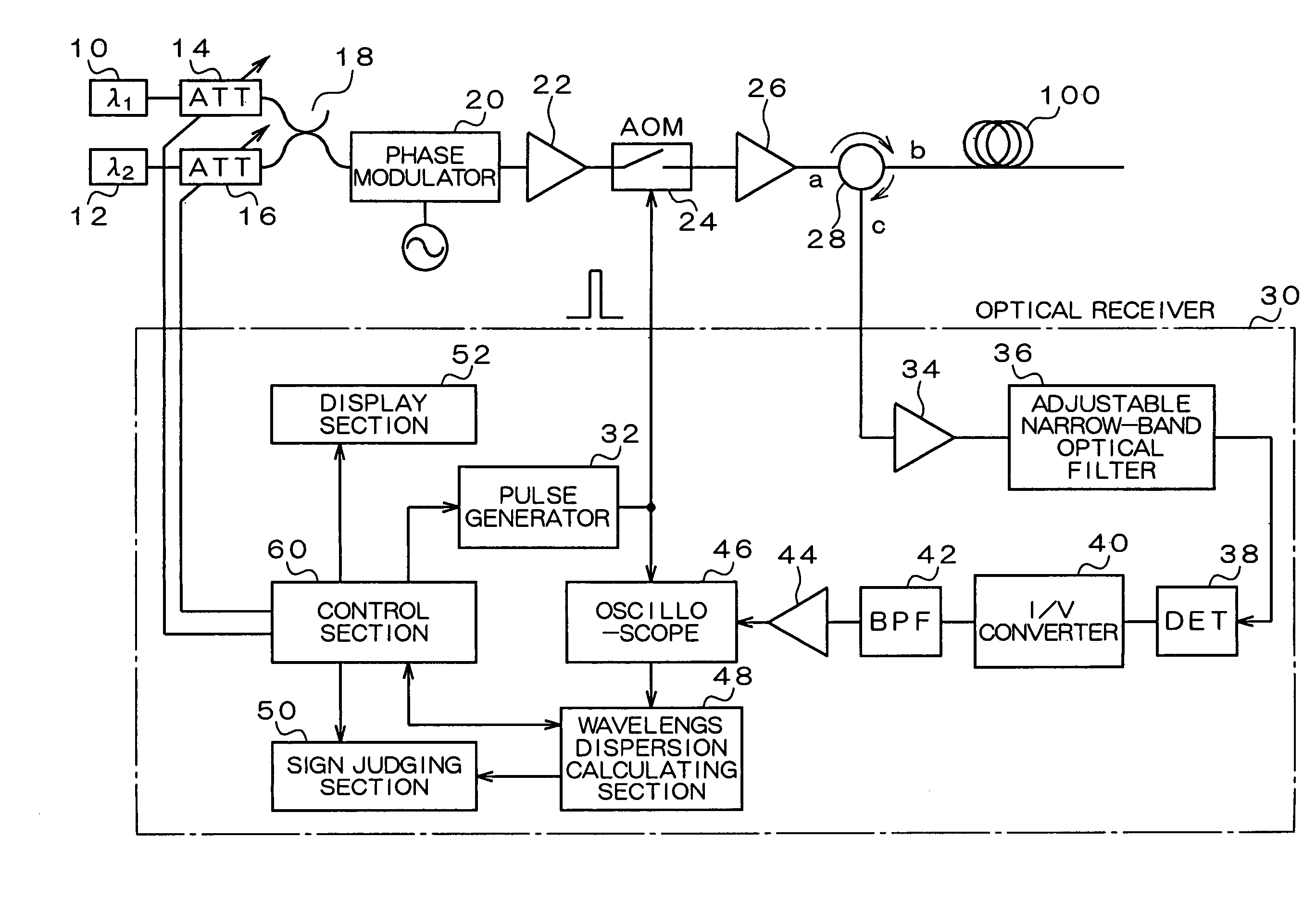
[0019]FIG. 1 is a diagram showing the structure of the wavelength dispersion probing system of an embodiment. The wavelength dispersion probing system shown in FIG. 1 is for determining the wavelength dispersion D and its sign of an optical fiber 100 as a fiber under test (FUT). This wavelength dispersion probing system comprises light sources 10 and 12, light attenuators 14 and 16, an optical multiplexer 18, a phase modulator 20, optical amplifiers 22 and 26, an acoustooptical modulator (AOM) 24, a circulator 28, and an optical receiver 30.

[0020]The two light sources 10 and 12 output continuation wave light (CW light) in wavelengths λ1 and λ2 which shift mutually by δλ, respectively. The light attenuator 14 adjusts the intensity of light in wavelength λ1, entered from the one light source 10, by adjustably changing the attenuation of the light,...


PUM

PropertyMeasurementUnit
frequencyaaaaaaaaaa
wavelengthaaaaaaaaaa

Abstract

A wavelength dispersion probing system for determining a value of wavelength dispersion and its sign and reducing the trouble and time required for this determination. This wavelength dispersion probing system comprises light sources 10, 12, light attenuators 14, 16, optical multiplexer 18, phase modulator 20, optical amplifiers 22, 26, acoustooptical modulator 24, optical receiver 30. The intensity ratio of two wavelengths is set at 1 to 2 to detect Stokes light or anti-Stokes light included in the return light of an optical fiber 100 by the optical receiver 30, so that wavelength dispersion is probed. The wavelength dispersion is probed by changing the intensity ratio of the two wavelengths to observe the state of the change of the wavelength dispersion, so that the sign of wavelength dispersion is determined by the optical receiver 30.

Description

TECHNICAL FIELD[0001]The present invention relates to a wavelength dispersion probing system which determines the wavelength dispersion and its sign of an optical fiber.BACKGROUND ART[0002]Generally, an optical fiber used for usage such as communication has wavelength dependency in a longitudinal direction. For this reason, in particular, in order to transmit a signal accurately by using an optical fiber used for a channel whose line length is long, it is necessary to take this wavelength dependency into consideration. What expresses this wavelength dependency is a “distributed map.” This distributed map shows the relationship between the distance in the longitudinal direction and the wavelength dispersion of an optical fiber. As prior art for determining a distributed map, an apparatus disclosed in Japanese Patent Laid-Open No. 10-83006 is known.[0003]The operation principle of this apparatus is to detect Stokes light or anti-Stokes light out of the return light which is obtained b...

Claims


Application Information

Patent Timeline
Patent Type & Authority Patents(United States)
IPC IPC(8): G02B6/26G01N21/00G01M11/00G01M11/02
CPCG01M11/3172G01M11/3163
Inventor SATOMURA, HIROAKIFUJITA, SHINYAUKITA, JUNICHIWATANABE, KATSUHIKO
Owner ADVANTEST CORP
Why Eureka
Try Eureka