
System and method for command transmission utilizing an email return path

a command transmission and email return technology, applied in the field of multi-computer data transmission, can solve the problems of limiting the network size to the quantity, affecting the practicality of the technique, and consuming time and energy

Active Publication Date: 2006-03-28
NYTELL SOFTWARE LLC
View PDF67 Cites 9 Cited by
  • Summary
  • Abstract
  • Description
  • Claims
  • Application Information

AI Technical Summary

Benefits of technology

"The present invention is a system and method that uses email protocols to create a return path for command and control interactions with outlying receiver sites. This allows for monitoring of a receiver network and identifying an alarm condition through a return path from a command. The system can also send an email to a central control system when an alarm condition occurs within an outlying receiver. The technical effects of this invention include improved monitoring and control of receiver networks, as well as faster and more efficient response to alarm conditions."

Problems solved by technology

This is a burdensome and time consuming technique.
This technique limits the network size to the quantity of devices that can be serviced by a central control system.
This technique is not practical due to the expense of necessary hardware to allow for multiple devices to transmit status information simultaneously.
Because of this, most computer systems severely limit the direct use of TCP / IP within their computer systems, except for certain well known applications such as electronic mail, through the use of a firewall.
Dawson, however, does not disclose an easy and reliable means of penetrating a firewall.
This method builds an additional TCP / IP layer on top of an electronic mail system that may communicate between computers and thus penetrates firewalls.
It does not disclose interactive communication with broadcast receivers via e-mail.
Gelman also does not disclose an easy and reliable means of penetrating a firewall.

Method used


Image

  • System and method for command transmission utilizing an email return path
  • System and method for command transmission utilizing an email return path
  • System and method for command transmission utilizing an email return path

Examples


Embodiment Construction

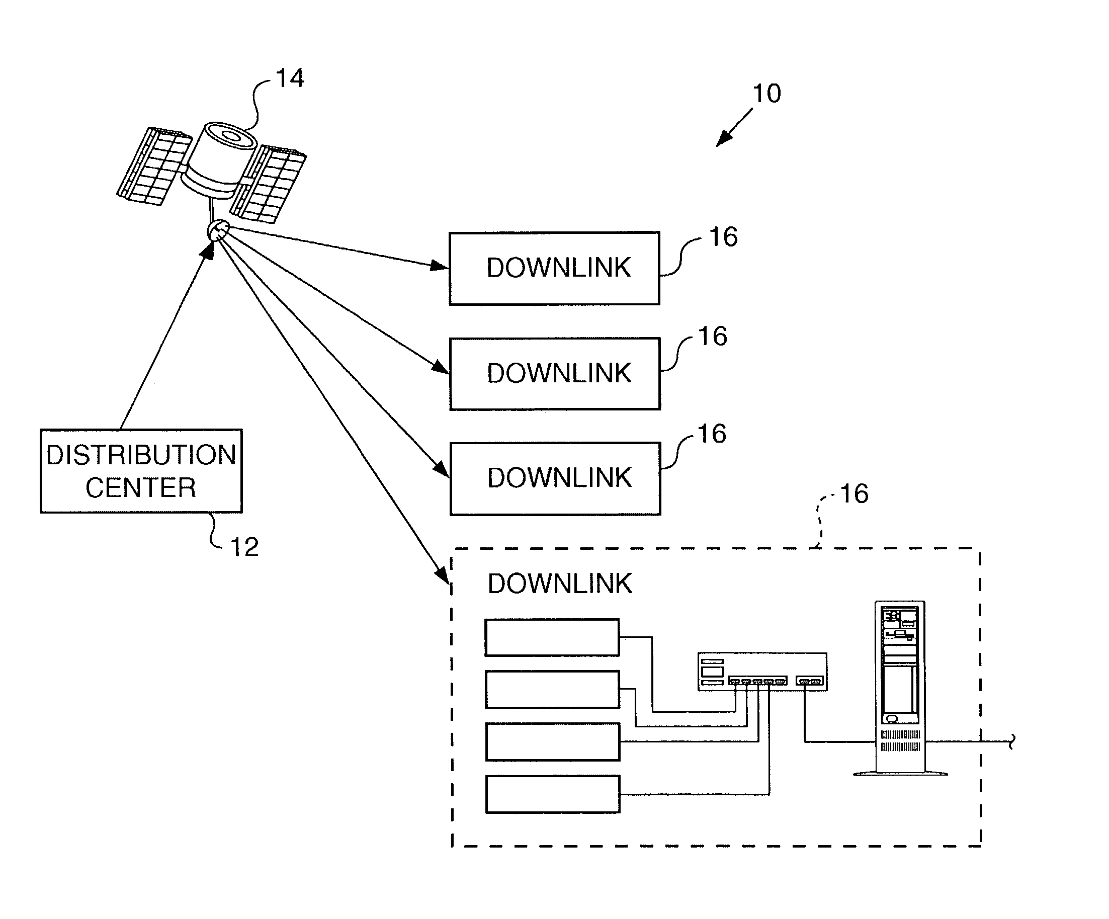
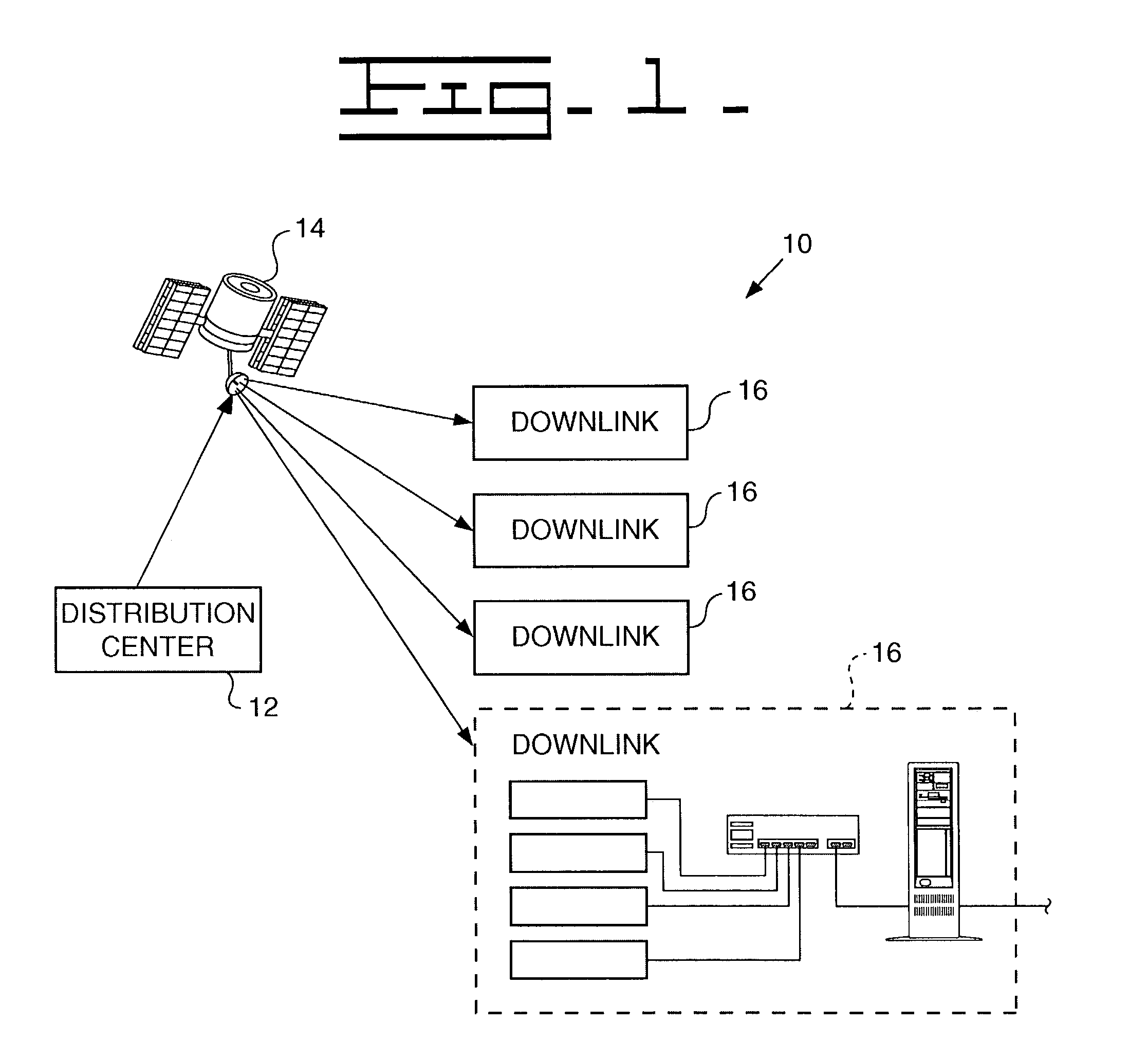
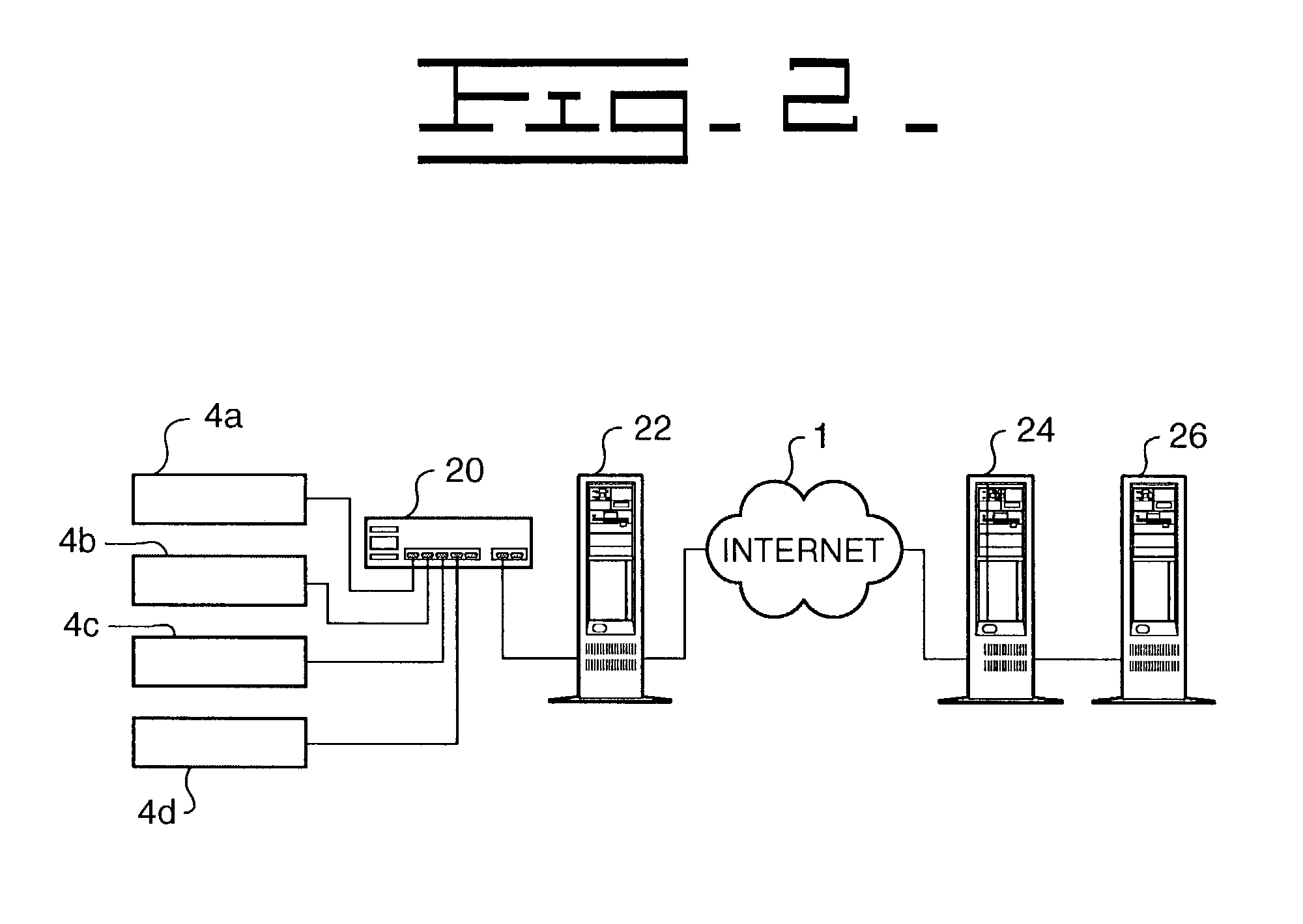
[0026]Referring to the accompanying drawings in which like reference numbers indicate like elements, FIG. 1 illustrates a typical satellite point to multipoint network 10 wherein the point is referred to as an uplink or distribution station 12 and the multipoints are called downlinks 16 with the equipment at each downlink 16 referred to as remote equipment, a remote location, or an integrated receiver / decoder. In the satellite control network 10, control information is generated at the distribution station 12 and transmitted via a satellite 14 to the downlinks 16. Control information is generated at the distribution station 12, fed to various conditioning and modulation circuits (not shown) and combined with other signals in a combiner (not shown). These other signals may be video signals or audio signals fed through an audio modulator to the combiner. These combined signals are transmitted by a transmitter (not shown) to a particular satellite on a particular frequency. The transmi...


PUM


Abstract

The system supports monitoring of receiver network status by providing an email return path for receiver status information. Remote locations provide access to an internet capable LAN, which the integrated receiver decoders use to send parameter information to the central server using the internet protocol. Unit status and parameter information is sent in a binary format using standard email protocols to transfer the data. The server translates the binary data and stores the receiver status, allowing the user to browse the latest status of any receiver which has sent back a report.

Description

CROSS-REFERENCE TO RELATED APPLICATIONS[0001]None.STATEMENT REGARDING FEDERALLY SPONSORED RESEARCH OR DEVELOPMENT[0002]Not Applicable.APPENDIX[0003]Not Applicable.BACKGROUND OF THE INVENTION[0004]1. Field of the Invention[0005]This invention relates generally to multiple computer data transferring and, more particularly, to a system and method using e-mail protocols for a return path for command and control interactivity with outlying receiver sites.[0006]2. Related Art[0007]Large communication networks transmit content data such as audio and video programming over a wide geographical area by satellite broadcast, terrestrial broadcast, cable or Internet. One type of satellite communication system is a point to multipoint configuration wherein transmission equipment at a single, central location, for example a satellite uplink, may send data, control information, audio and video signals to hundreds or even thousands of individual locations multiple receiving stations such as satellit...

Claims


Application Information

Patent Timeline
Patent Type & Authority Patents(United States)
IPC IPC(8): G06F15/16H04L12/58H04L29/06
CPCH04L29/06H04L51/18H04L51/02H04L51/066H04L69/22H04L51/08H04L9/40
Inventor SIMYON, JEFFPLACEK, DAVID M.KENNEDY, JOSEPH L.
Owner NYTELL SOFTWARE LLC
Learn More