Toilets with quick flush trapways

a trapway and toilet technology, applied in water installations, water closets, constructions, etc., can solve the problems of reducing the flushing cycle time, reducing the flushing efficiency of toilets, so as to reduce the waste of water, improve the flushing cycle time, and quick fill key portions

Inactive Publication Date: 2006-04-04
KOHLER CO
View PDF8 Cites 10 Cited by
  • Summary
  • Abstract
  • Description
  • Claims
  • Application Information

AI Technical Summary

Benefits of technology

[0017]The present invention thus provides a toilet with a unique trapway design. It is designed so that water from the bowl completely and quickly fills key portions of the trapway during a flush cycle. This leads to rapid evacuation of the bowl contents, minimizing water waste. The trapway design improves the full flush cycle time and significantly improves the rate of the flushing action to nearly half that of common gravity driven toilets with conventional trapway designs.
[0018]The rearwardly slightly canted down leg reduces the formation of air pockets in the water dam region which would otherwise interfere with the siphoning effect of the trapway. The baffle ledge breaks up the water passing from the down leg to entrain air and particles, and further promote their rapid evacuation through the trapway. The uniform circular cross-section of the curved water dam region helps to lift the surface of the fluid at the water dam during siphon initiation, which further helps to remove air.

Problems solved by technology

However, for environmental and water conservation reasons many jurisdictions now restrict the sales of toilets which use too much water per flush.
Achieving an effective flush with that little water when the bowl is filled with feces, toilet paper, and other solids can be difficult.
This not only frustrates the regulatory and conservation goals, it is time consuming for consumers.
However, attempts to develop quick flush action having efficient cleaning with low volumes of water can be frustrated by “blow back”, which is a tendency of such trapways to develop reverse flow of air from the plumbing lines into a low pressure region of the trapway.

Method used


Image

  • Toilets with quick flush trapways
  • Toilets with quick flush trapways
  • Toilets with quick flush trapways

Examples


Embodiment Construction

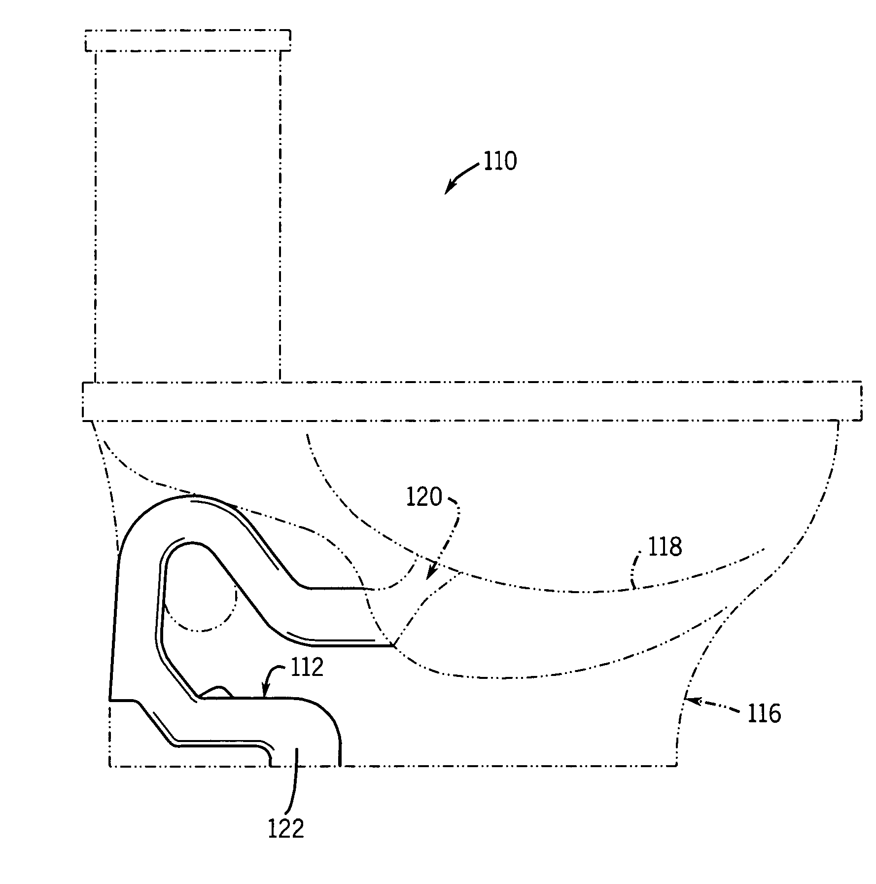
[0036]FIG. 1 illustrates a toilet 10 having a siphon passage or trapway 12 design according to the present invention. In particular, other than the trapway 12, the toilet 10 can be any suitable toilet, preferably of a low volume flush design.

[0037]For example, FIG. 1 shows in hidden lines a two-piece type toilet having a separate flush tank 14 mounted to a bowl base 16. A hole (not shown) in the bottom of the flush tank 14 aligns with a hole (not shown) in the top of the bowl base 16 to allow water to pass from the flush tank and into the a bowl 18, formed in the bowl base 16, during a flush cycle.

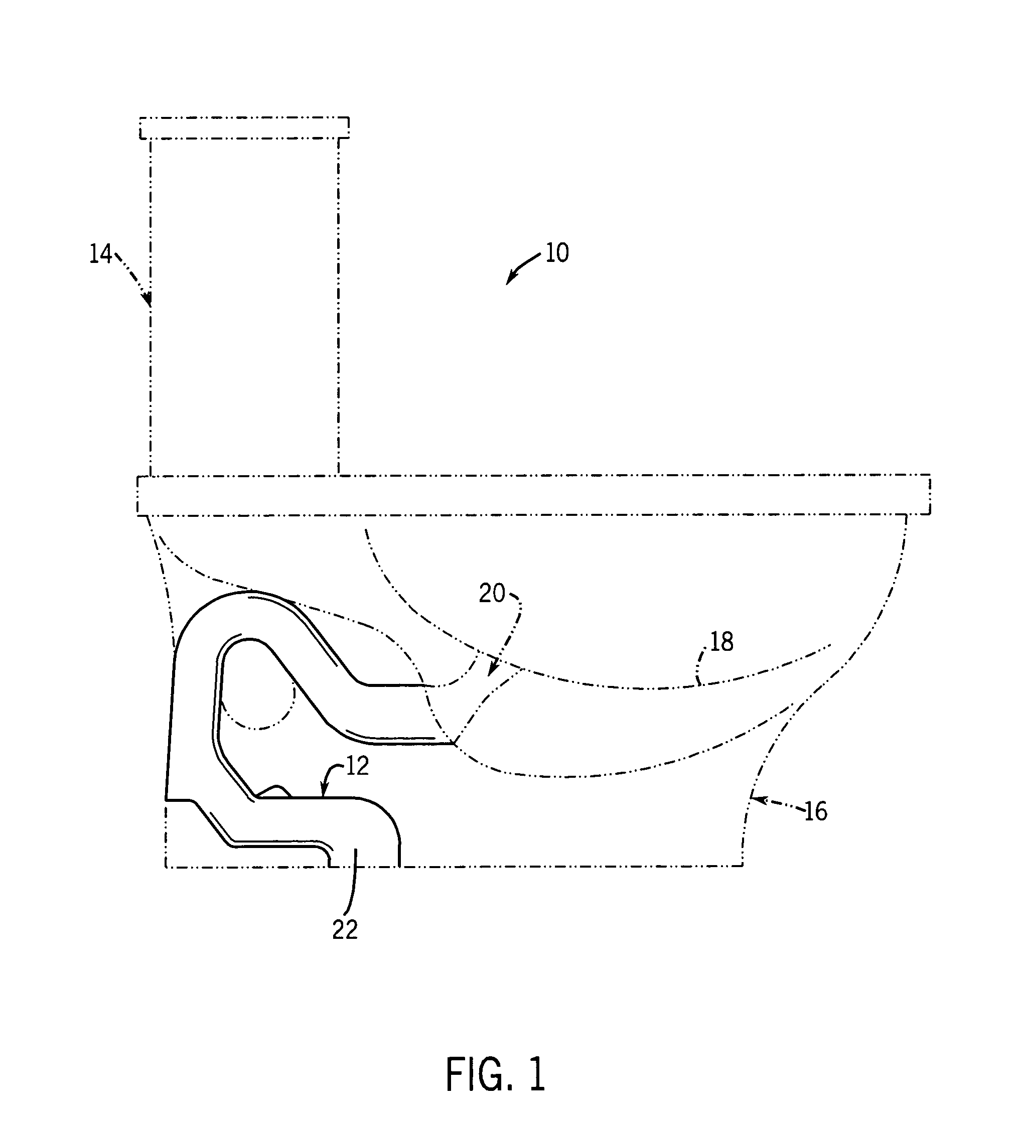
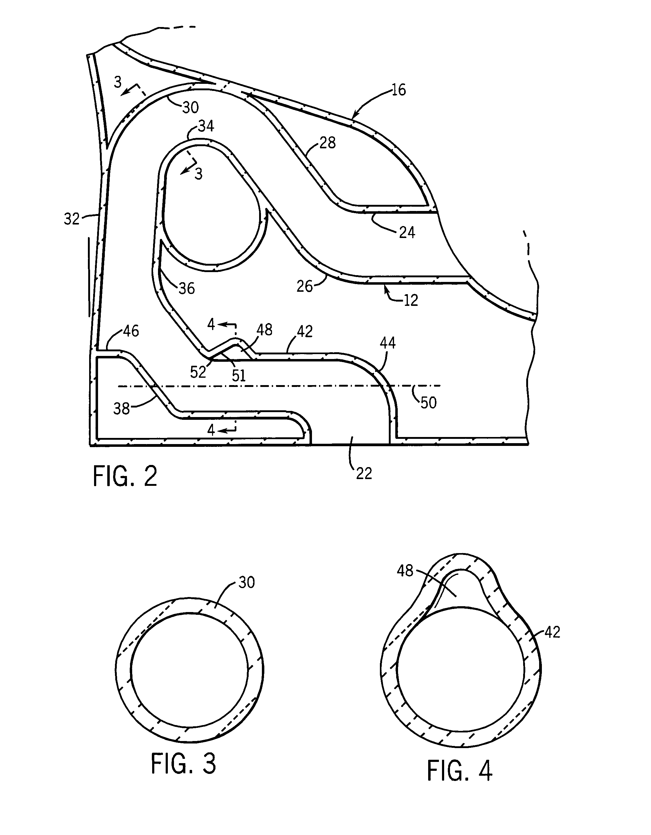
[0038]The trapway 12 extends from an opening 20 in the bowl 18 along a serpentine path, having for much of its length an essentially uniform and constant circular cross-section (as shown in FIG. 3). This cross-section is present at least in the second bend 30 at the dam 34.

[0039]The trapway has an outlet opening 22 at the bottom of the base of bowl 16, which mounts over the open end of a w...


PUM


Abstract

A toilet has a trapway extending between a bowl opening and an outlet opening. The trapway defines a curved, preferably uniform circular cross-section water dam region above the bowl opening, a down leg, and a straight out leg between the down leg and the outlet opening. The down leg has a rearward slope where is located a horizontal baffle. The inclined down leg and horizontal baffle work in concert to prevent the back flow of air to a region above the dam as well as to facilitate rapid entrainment and evacuation of air below the dam.

Description

CROSS-REFERENCE TO RELATED APPLICATION[0001]This application is a continuation-in-part of U.S. application Ser. No. 10 / 347,740, now U.S. Pat. No. 6,944,891, filed Jan. 20, 2003.STATEMENT OF FEDERALLY SPONSORED RESEARCH OR DEVELOPMENT[0002]Not applicable.BACKGROUND OF THE INVENTION[0003]The present invention relates to toilets provided with improved trapways.[0004]Conventional toilets have a bowl portion and a storage tank portion, usually formed in one or two main pieces. A serpentine passage is typically positioned behind and below the bowl to transport the contents of the bowl to waste / sewer / septic plumbing lines of the building. This passage is generally referred to as the “siphon” or “trapway”.[0005]An up leg portion of such a passage is normally filled with water to “trap” sewer gases downstream thereof, so as to prevent them entering the building interior. Water is maintained in the bowl and the up leg part of the trapway by an arched portion of the trapway. The trapway (somet...

Claims


Application Information

Patent Timeline
Patent Type & Authority Patents(United States)
IPC IPC(8): E03D11/00E03DE03D11/02E03D11/18
CPCE03D11/18E03D11/02
Inventor KURU, WILLIAM C.KRISHNAMURTY, VENKATA S.HALLORAN, DANIEL N.LIU, PATRICK YING-TEMUKERJI, SUDIP
Owner KOHLER CO
Why Eureka
Try Eureka