Cooling tube for cooling a portion of an injection molded article

a technology of injection molding and cooling tubes, which is applied in the field of cooling tubes, can solve the problems of high robot technical specifications, high production costs, and high energy consumption of robots, and achieve the effects of reducing robot specification requirements, improving cooling efficiency, and easy manufacturing

Inactive Publication Date: 2005-07-12
HUSKY INJECTION MOLDING SYST LTD
View PDF15 Cites 27 Cited by
  • Summary
  • Abstract
  • Description
  • Claims
  • Application Information

AI Technical Summary

Benefits of technology

[0015]According to a fourth aspect of the present invention, a tube assembly includes a tubular porous insert for vacuum forming a molded article, and to improve cooling efficiency. The porous insert includes an inner surface that is contoured to substantially correspond with the final desired molding surface of the molded article. Pressure channels in the porous insert provide a conduit for establishing a region of relatively low vacuum pressure and for evacuating air through the porous structure of the porous insert, thereby drawing a deformable molded article into contact with the contoured inside surface.
[0016]In its preferred embodiment, the present invention advantageously provides an extruded cooling tube that is easily manufactured and which is of a lightweight construction that, beneficially, reduces robot specification requirements and / or improves robot cycle time. Futhermore, the cooling tube has enhanced cooling capabilities as a consequence of improved and integrally formed channeling. In addition, alternative embodiments of the present invention provide tube assemblies that are capable of vacuum forming a molded article.

Problems solved by technology

More specifically, while one injection cycle is taking place, the post mold cooling system, typically acting in a complementary fashion with a robotic part removal device, is operative on an earlier formed set of molded articles that have been removed from the mold at a point where they are still relatively hot, but sufficiently solid to allow limited handling.
A problem with known cooling tubes is that they are expensive and are time-consuming to make and assemble.
Moreover, the robot typically operates to remove many tens of preforms in a single cycle (with present PET systems producing up to one hundred and forty-four preforms per injection cycle) so the energy expended by the robot and the technical specification of the robot are unfortunately relatively high.
The provision and operation of a high specification robot therefore impose considerable financial cost penalties on an end user.

Method used


Image

  • Cooling tube for cooling a portion of an injection molded article
  • Cooling tube for cooling a portion of an injection molded article
  • Cooling tube for cooling a portion of an injection molded article

Examples


Embodiment Construction

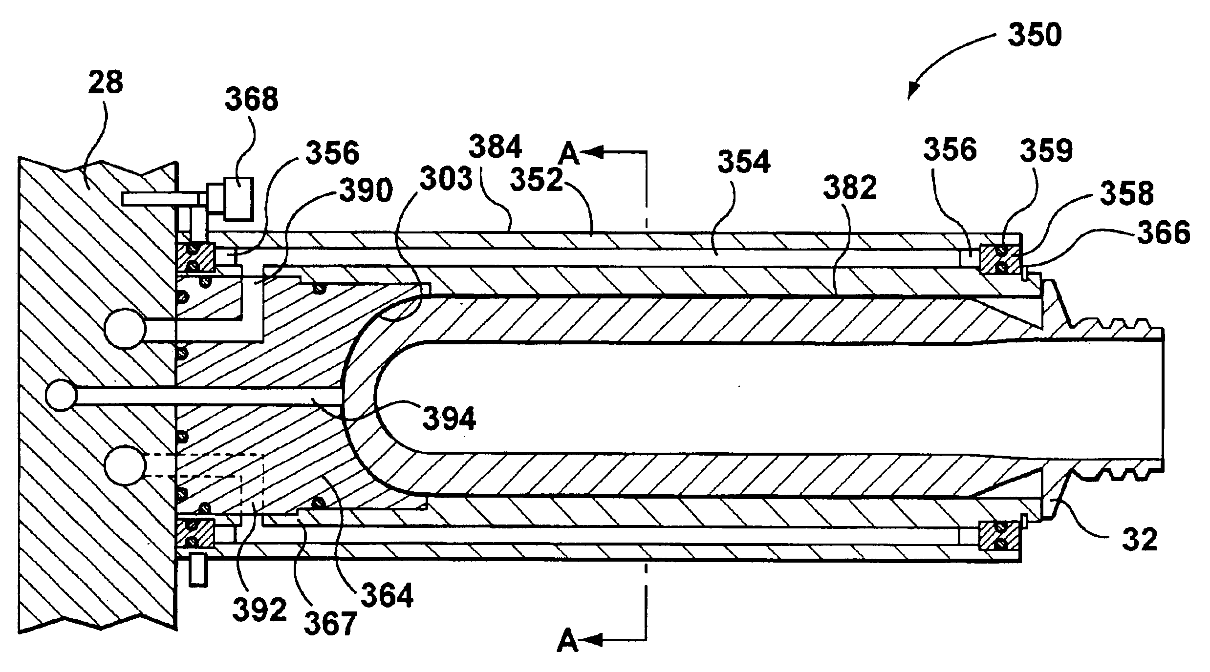
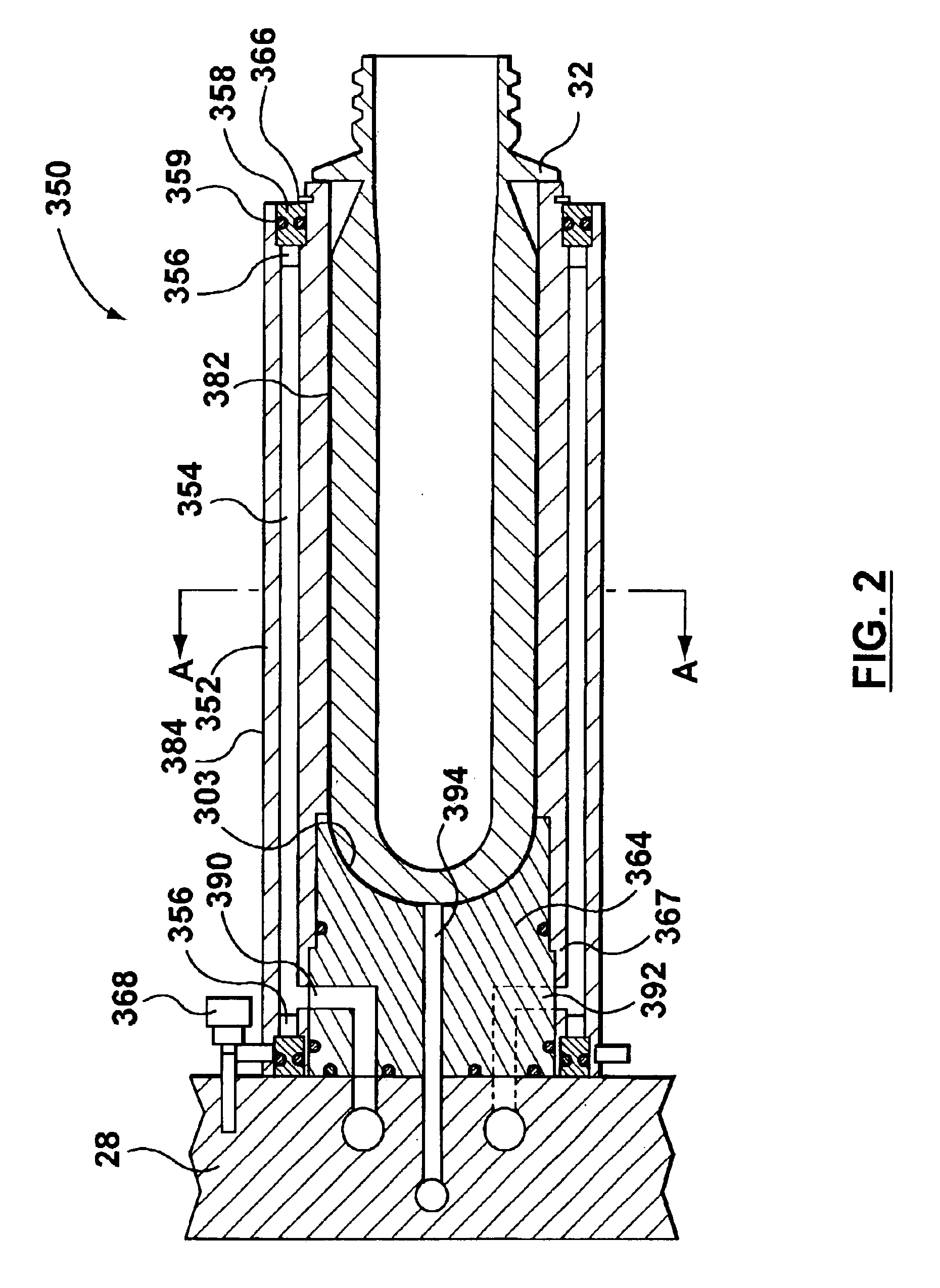
[0023]The present invention will now be described with respect to embodiments in which an extruded cooling tube is used in a plastic injection molding machine, although the present invention is equally applicable to any technology in which, following part formation, cooling of that part is undertaken by a cooling tube or the like. For example, the present invention can find application in a part transfer mechanism from an injection molding machine and a blow-molding machine.

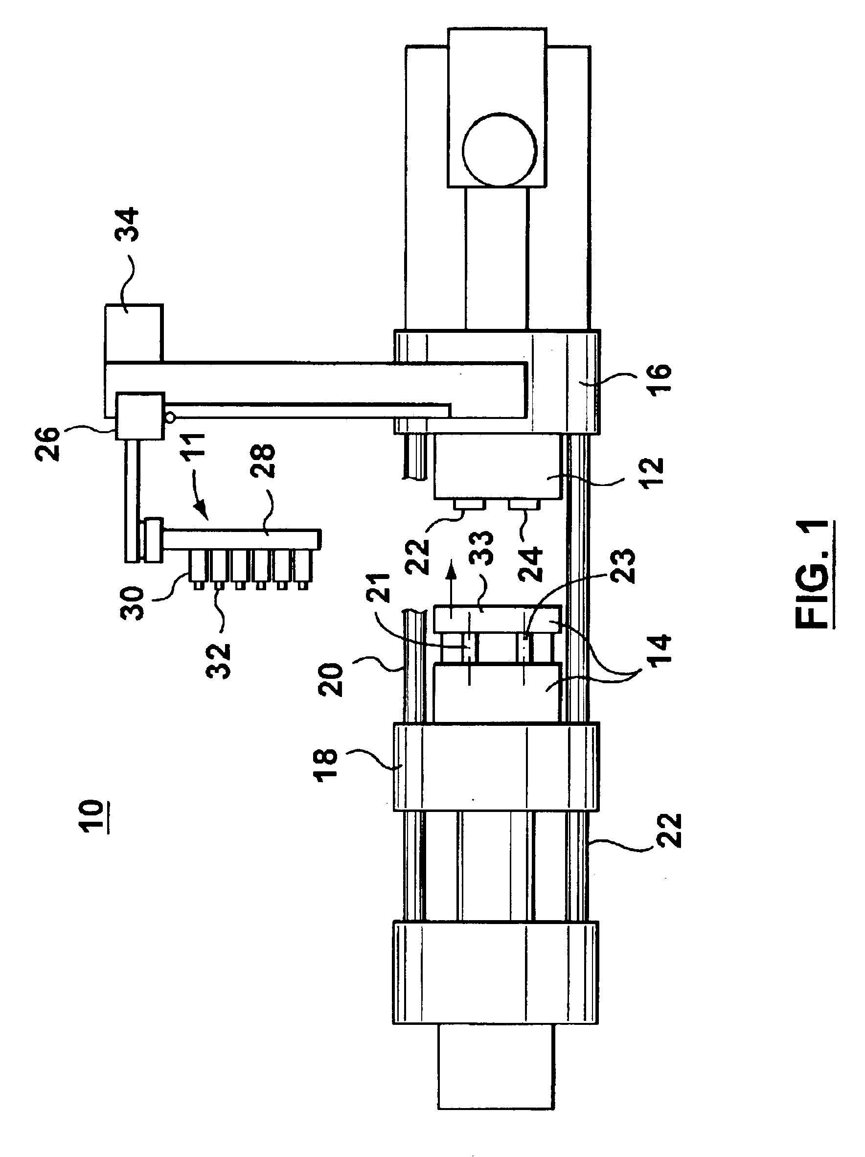
[0024]FIG. 1 shows a typical injection molding machine 10 capable of co-operating with a device supporting the cooling tube of the present invention. During each injection cycle, the molding machine 10 produces a number of plastic preforms (or parisons) 32 corresponding to the number of mold cavities defined by complementary mold halves 12, 14 located within the machine 10.

[0025]The injection-molding machine 10 includes, without specific limitation, molding structure such as a fixed platen 16 and a movable platen...


PUM

PropertyMeasurementUnit
outer diameteraaaaaaaaaa
lengthaaaaaaaaaa

Abstract

An injection-molded plastic part cooling tube has an extruded cylindrically shaped tube with an inside surface and an outside surface. An extruded cooling channel is disposed inside the cylindrically shaped tube, between the inside surface and the outside surface. A method for forming an injection-molded-plastic-part cooling tube includes the step of extruding a hollow aluminum tube having an inside surface, an outside surface, and at least one cooling channel in the hollow aluminum tube between the inside surface and the outside surface. Alternative cooling tubes include a tubular porous insert for vacuum forming molded articles.

Description

[0001]This is a continuation-in-part application of application Ser. No. 10 / 246,916, filed Sep. 19, 2002, now U.S. Pat. No. 6,737,007 the contents of which are therefore incorporated herein by reference.BACKGROUND OF INVENTION[0002]1. Field of the Invention[0003]The present invention relates, in general, to cooling tubes and is particularly, but not exclusively, applicable to cooling tubes used in conjunction with a plastic injection-molding machine to cool plastic parts, such as plastic parisons or preforms. More particularly, the present invention relates to a structural configuration of these cooling tubes, and also to methods of manufacturing and using such tubes, for example in the context of a manufacturing process for preforms made from polyethylenetetraphthlate (PET) or the like.[0004]2. Summary of the Prior Art[0005]In the injection molding art, it is known to use post mold cooling systems that operate simultaneously with the injection molding cycle. More specifically, whil...

Claims


Application Information

Patent Timeline
Patent Type & Authority Patents(United States)
IPC IPC(8): B29C45/00B29C49/64B29C45/72B29C47/20B29C49/42B29C35/00B29C35/16B29C49/06B29C48/09B29C48/32
CPCB29C45/0053B29C45/7207B29C47/0028B29C47/12B29C49/4205B29C49/6427B29C47/0054Y10T428/1352B29C2035/1616B29C2045/7214B29L2031/60B29C49/06B29C48/11B29C48/0017B29C48/09B29C2949/0715B29C2049/023
Inventor ROMANSKI, ZBIGNIEWURACZ, TOMASZUNTERLANDER, RICHARD MATTHIASNETER, WITOLDNIEWELS, JOACHIM JOHANNES
Owner HUSKY INJECTION MOLDING SYST LTD
Why Eureka
Try Eureka