Diesel exhaust aftertreatment device regeneration system

a technology of exhaust gas aftertreatment and regeneration system, which is applied in the direction of machines/engines, combustion types, lighting and heating apparatus, etc., can solve the problems of carbon buildup in the exhaust system, fuel may be completely oxidized or generated smoke, and fuel may be wasted, so as to reduce the temperature of the fuel injector and improve the effect of vaporization

Active Publication Date: 2006-04-04
GM GLOBAL TECH OPERATIONS LLC
View PDF8 Cites 45 Cited by
  • Summary
  • Abstract
  • Description
  • Claims
  • Application Information

AI Technical Summary

Benefits of technology

[0006]The present invention provides an improved diesel exhaust aftertreatment device regeneration system, which reduces fuel injector temperatures and improves vaporization of after injected fuel during an aftertreatment regeneration event.
[0011]During engine operation, exhaust gas flowing through the exhaust gas aftertreatment system first heats the vaporization member and then passes through the DOC to the CDPF, in which carbon particulates are trapped while the cleaned exhaust gas passes through. After a period of time or operating interval in which carbon particulates build up in the CDPF, the ECM activates the fuel injector, causing atomized fuel to spray onto the vaporization member. As the atomized fuel sprayed from the injector makes contact with the heated vaporization member, the fuel is vaporized and mixes with the exhaust gas. As the exhaust gas carries the vaporized fuel through the exhaust conduit toward the aftertreatment device, the baffles extend the mixing path and improve fuel vaporization.

Problems solved by technology

However, as the engine runs rich, fuel may be wasted and the additional fuel may be completely oxidized or generate excess smoke before the reducing agents are used to regenerate the NAC.
However, depending upon timing and engine operating conditions, the after injected fuel may be completely oxidized or generate smoke before the fuel vapor reaches the CDPF.
However, depending on exhaust gas temperatures, injected fuel may not fully vaporize, resulting in the formation of carbon buildup in the exhaust system.

Method used


Image

  • Diesel exhaust aftertreatment device regeneration system
  • Diesel exhaust aftertreatment device regeneration system
  • Diesel exhaust aftertreatment device regeneration system

Examples


Embodiment Construction

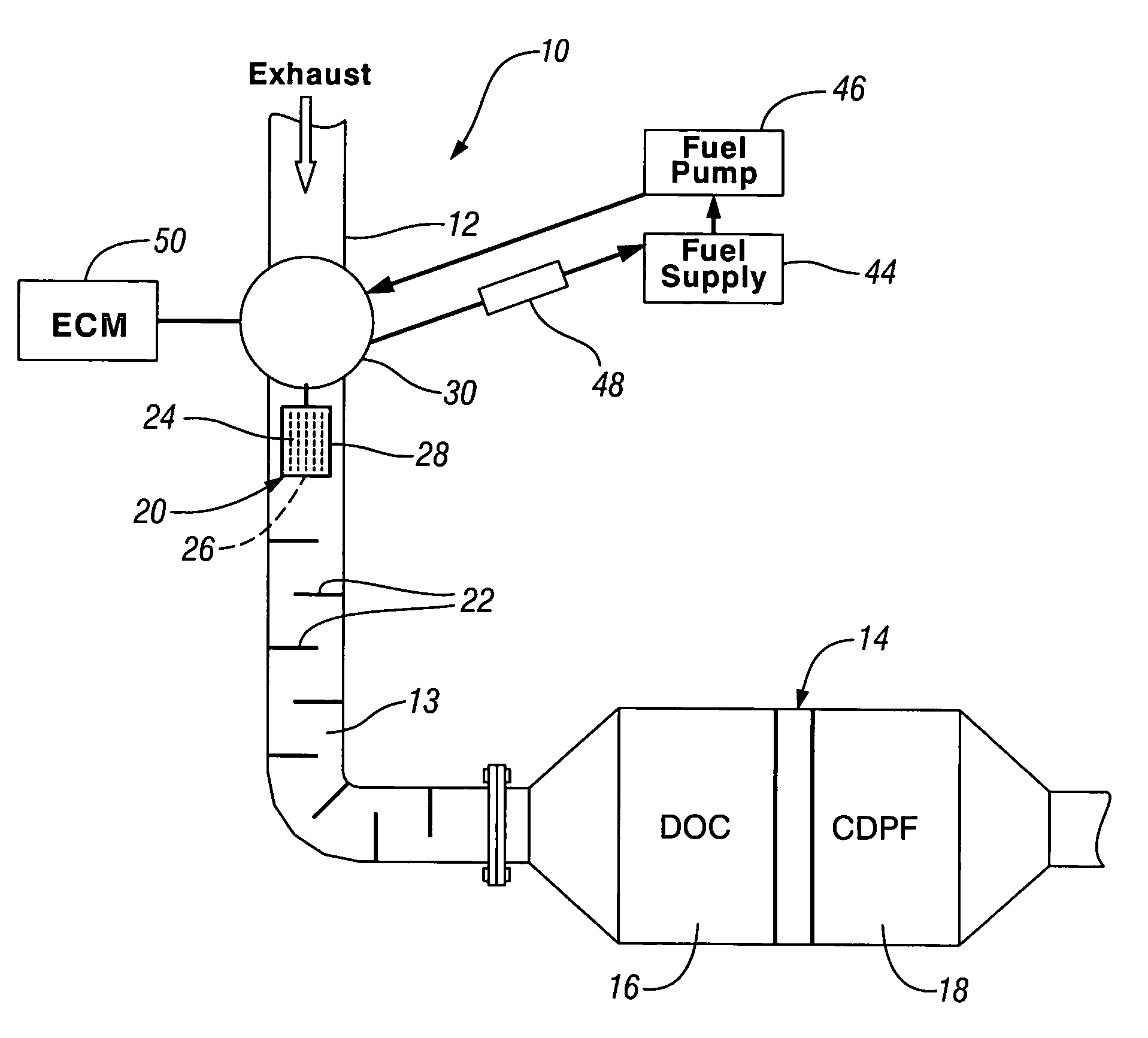
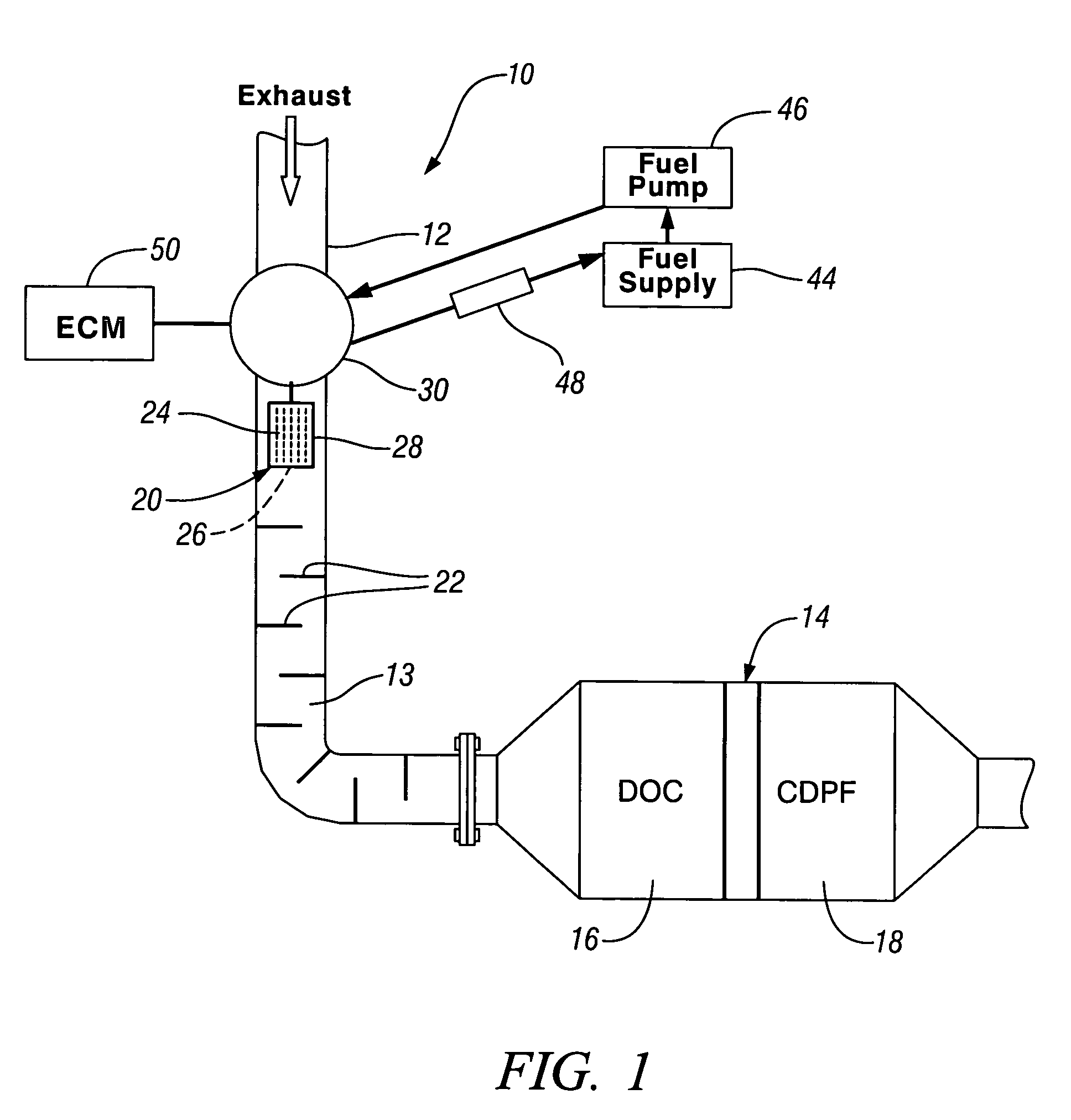
[0016]Referring first to FIG. 1 of the drawings in detail, numeral 10 generally indicates a diesel exhaust emission control device regeneration system for regenerating an emission control device in an exhaust system for an internal combustion diesel engine. The system 10 includes an exhaust conduit 12, defining an internal passage 13, adapted to carry exhaust gas to an exhaust gas aftertreatment device 14, such as a diesel oxidation catalyst 16 (DOC) mounted ahead of a catalyzed diesel particulate filter 18 (CDPF). The exhaust conduit 12 includes an internal fuel vaporization member 20 positioned upstream from the aftertreatment device 14 and a plurality of internal baffles 22 intermediate the vaporization member and the aftertreatment device.

[0017]The vaporization member 20 is preferably a horizontally extending plate 24 supported within the exhaust conduit 12 by a connecting support 26. If desired, the plate 24 may have an upturned peripheral rim 28 operative to temporarily retain...


PUM


Abstract

A diesel exhaust aftertreatment device regeneration system includes an exhaust conduit adapted to conduct exhaust gas to an exhaust gas aftertreatment device. The system further includes a low pressure bottom feed fuel injector having an inlet portion fully received within a chamber of an adaptor housing having a lower portion attached to the exhaust conduit. The housing is provided with fuel flow openings to allow low pressure fuel to circulate around and cool the fuel injector inlet portion within the chamber. Fuel injected into the exhaust conduit is preferably targeted toward a vaporization member, within the exhaust conduit, operative to absorb heat from the exhaust gas and vaporize fuel deposited thereon. A plurality of inwardly extending mixing baffles within the exhaust conduit intermediate the vaporization member and the aftertreatment device extend the mixing path to improve fuel vaporization for assisting regeneration of the device.

Description

TECHNICAL FIELD[0001]This invention relates to regeneration in operation of exhaust gas aftertreatment devices and, more particularly, to an exhaust fuel injection system for initiating such regeneration.BACKGROUND OF THE INVENTION[0002]Diesel aftertreatment devices such as catalyzed diesel particulate filters (CDPF) and NOx adsorber catalysts (NAC) are known in the art for controlling diesel engine emissions. During diesel engine operation, oxides of nitrogen and carbon particulates are produced as byproducts of combustion. These materials are subsequently collected by the NAC and the CDPF. As the oxides of nitrogen and carbon particulates accumulate within these aftertreatment devices, the aftertreatment devices must be regenerated. This is accomplished by reducing the oxides of nitrogen and oxidizing the carbon particulates held by these devices.[0003]NAC devices are commonly regenerated by running the diesel engine rich, a few seconds for every minute of engine operation, to pro...

Claims


Application Information

Patent Timeline
Patent Type & Authority Patents(United States)
IPC IPC(8): F01N3/00
CPCF01N3/0253F01N3/035F01N3/2066F01N3/36F01N13/08F01N13/0097F01N2240/20F01N2610/03F01N2610/102F01N2610/11F01N2610/1473Y02T10/20Y02T10/24F01N2260/024Y02T10/12
Inventor HILDEN, DAVID L.CRELLIN, CHRIS C.
Owner GM GLOBAL TECH OPERATIONS LLC
Why Eureka
Try Eureka