Exhaust heat recovery system

a heat recovery system and exhaust heat technology, applied in the direction of lighting and heating apparatus, machines/engines, heating types, etc., can solve the problems of easy increase of installation costs, excessive rise of water temperature in the system, and large system as a whole, so as to prevent the blockage of open-air pipes, maintain the heat maintaining effect of the lid, and reduce the effect of rough movement of the lid accompanying the steam release of the heating medium

Inactive Publication Date: 2006-04-04
THE TOKYO ELECTRIC POWER CO INC
View PDF20 Cites 8 Cited by
  • Summary
  • Abstract
  • Description
  • Claims
  • Application Information

AI Technical Summary

Benefits of technology

[0024]In this case, at the upper face of the lid, it is better to provide a block-preventing part that prevents blocking of the open-air pipe accompanying the movement of the lid.
[0025]By providing the block-preventing part at the upper face of the lid, even when the lid moves along with the movement of the water surface inside the tank, blocking of the open-air pipe can be prevented.
[0026]In addition, at the under face of the lid, it is better to provide an overturn-preventing part which prevents overturn and reverse of the lid.
[0027]By providing the overturn-preventing part, even when the lid moves along with the movement of the water surface inside the tank, the reverse and overturn of the lid is prevented, and the heat maintaining effect of the lid is maintained.
[0028]In addition, it is better to provide a gap between the internal wall of the tank and the lid to limit the rough movement of the lid accompanying a steam release of said heating medium.
[0029]By providing a gap between the internal wall and the lid, rough movement of the lid accompanying the steam release of the heating medium is limited, and the heat maintaining effect by the lid is stably maintained.

Problems solved by technology

In addition, in the exhaust heat recovery system described above, when the use of water (hot water) that circulates through the secondary pipes 511 is low, the temperature of water (hot water) in the system rises excessively.
In the exhaust heat recovery system described above, there are problems in that the cooling facility formed by the heat exchanger 506 for hot water supply temperature adjustment and the cooling tower 507 are necessary, and thereby the system as a whole becomes complicated and large, and the costs for the installation easily increase.

Method used


Image

  • Exhaust heat recovery system
  • Exhaust heat recovery system
  • Exhaust heat recovery system

Examples


Embodiment Construction

[0043]The embodiments of the exhaust heat recovery system of the present invention will be explained below with reference to the figures.

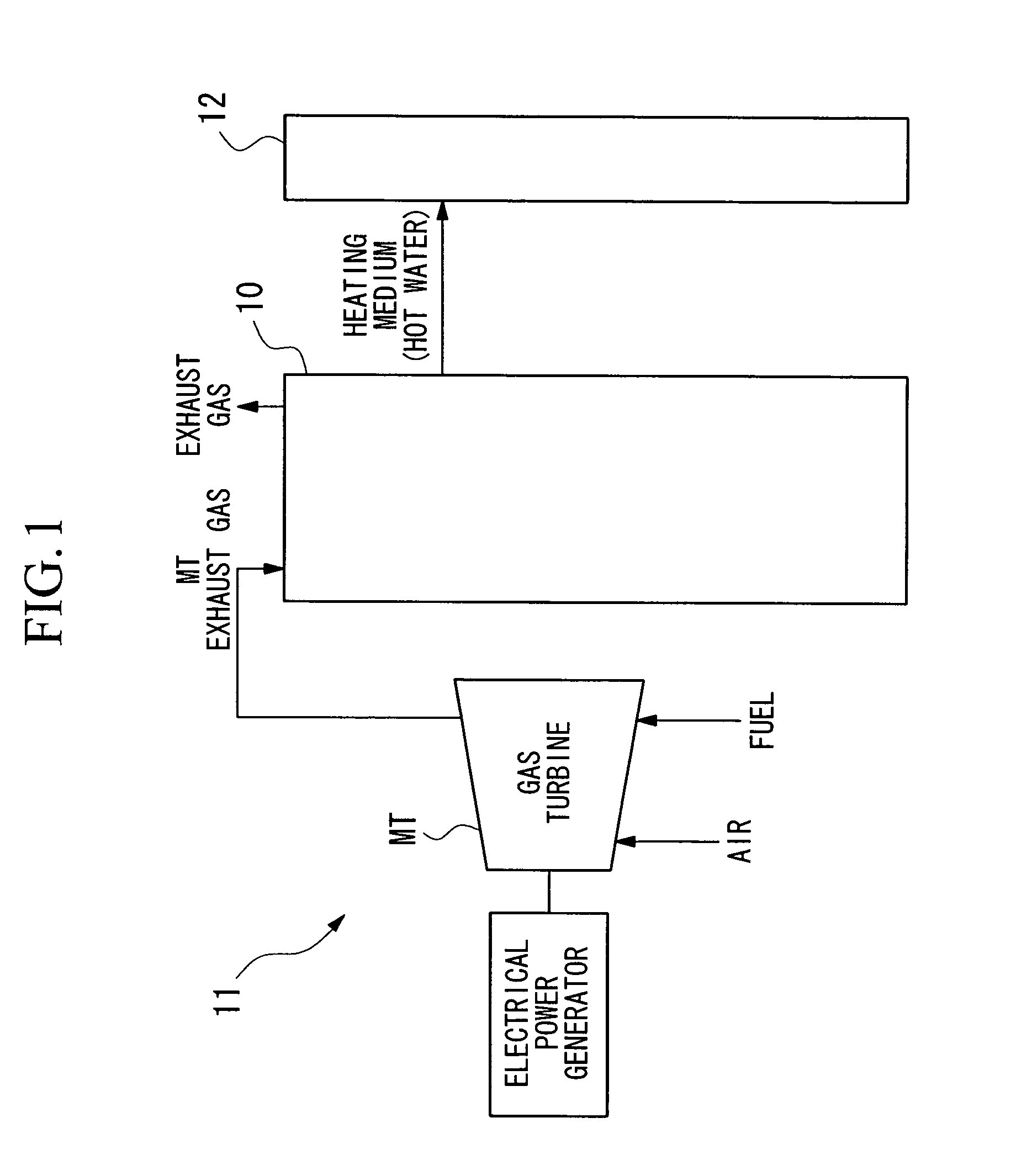
[0044]FIG. 1 schematically shows the entire structure of the self-contained type electrical power supply system 11 into which the exhaust heat recovery system 10 has been incorporated. The self-contained type electrical power supply system 11 itself obtains electrical power by driving an electrical power generator using a small sized gas turbine (micro gas turbine) MT as a drive source, while the exhaust heat recovery system 10 that is attached thereto captures the heat of the exhaust gas generated by the gas turbine MT when driving the electrical power generator, and this is used in predetermined facilities 12 such as air conditioning and hot water supply.

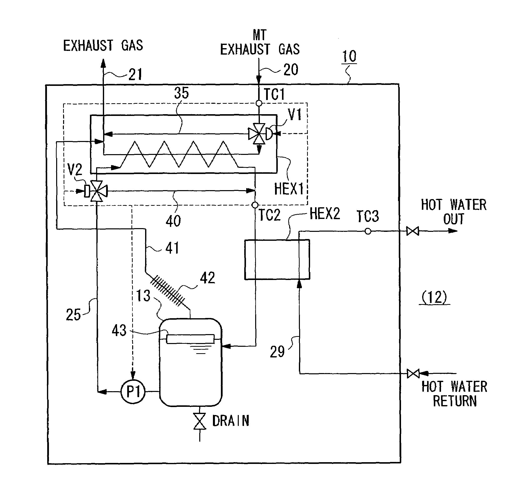
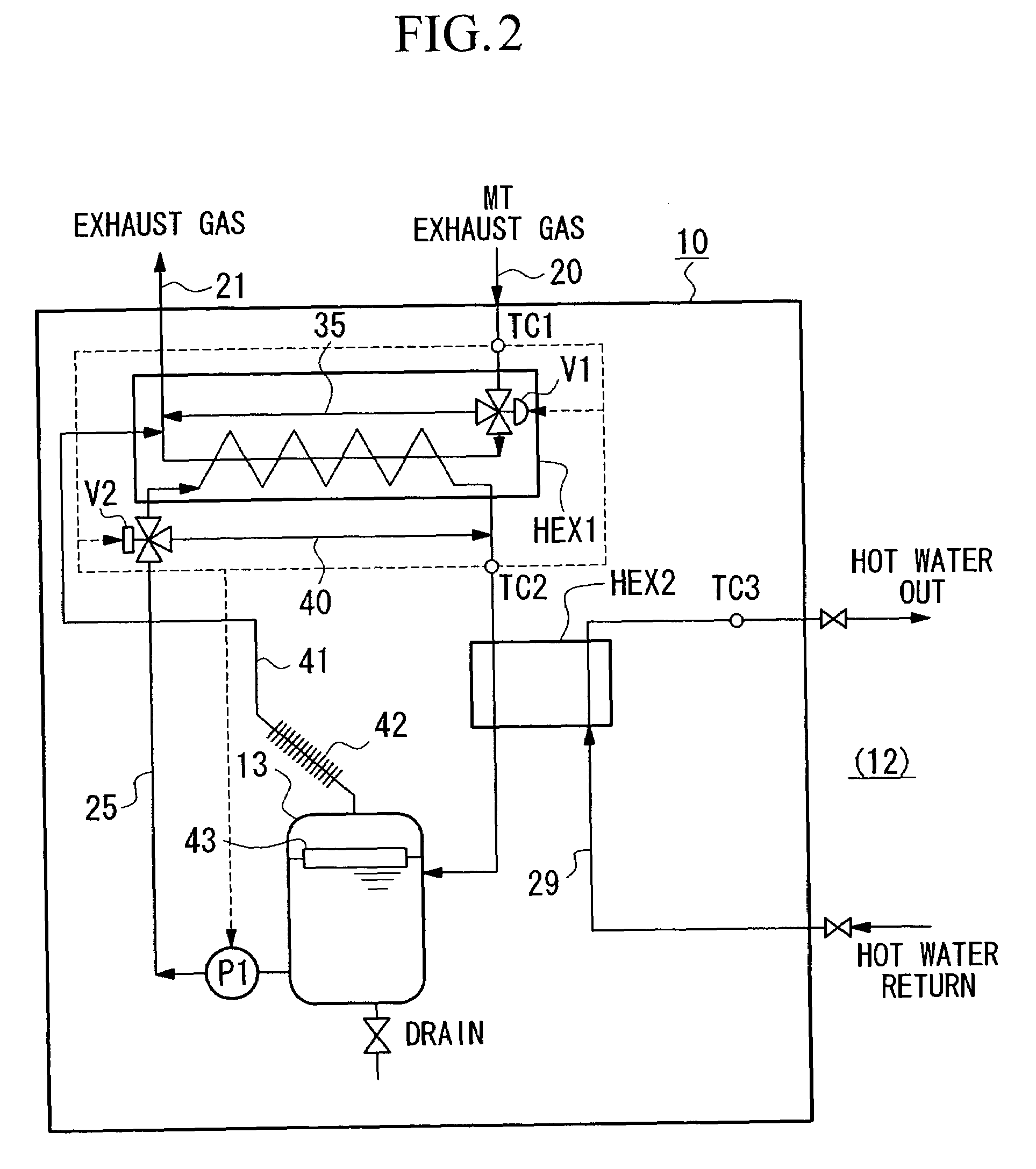
[0045]FIG. 2 is a drawing showing the structure of the embodiment of the exhaust heat recovery system 10. In the exhaust heat recovery system 10 of the present embodiment, the water (hot water) u...


PUM


Abstract

The present invention relates to an exhaust heat recovery system that recovers exhaust heat that is generated by an electrical power generator for use in supplying hot water and air conditioning, and has as an object of providing an exhaust heat recovery system that realizes reduced costs and has a high energy efficiency. The exhaust heat recovery system provides a heat exchanger HEX1 for exhaust heat recovery that heats heating medium by heat exchange between exhaust gas generated at the power generator and heating medium that is circulated and used in a predetermined facility. In addition, the exhaust heat recovery system comprises a tank 13 that temporarily stores the heating medium, and an open-air pipe 41 that releases the contents of the tank 13.

Description

TECHNICAL FIELD[0001]The present invention relates to an exhaust heat recovery system that recovers exhaust heat that is generated by an electrical power generator for use in supplying hot water and air conditioning.[0002]The present application is based on Japanese Patent Application, No. 2001-369357, the contents of which are incorporated herein by reference.BACKGROUND ART[0003]In recent years, in relatively small-scale areas such as office buildings, industrial facilities, and the like, electrical power generators are driven by using drive sources which use gas, oil, or the like, as a fuel, and there is a trend to use systems that self-contained electrical energy. In particular, as a drive source for an electrical power generator, the technology used in small-scale gas turbines that are driven using low cost fuel and have a low noise level has been progressing, its flexibility has been increasing, and thus there is a trend to expand the use of these.[0004]There are many cases in ...

Claims


Application Information

Patent Timeline
Patent Type & Authority Patents(United States)
IPC IPC(8): F02G1/00F02G5/02F24D18/00
CPCF02G5/02F24D11/005F24D2200/26Y02T10/166F28D20/0034F28D21/0003F28D2020/0095F24H2240/06Y02T10/12F24D2101/10F24D2103/13F24D18/00F24D2103/17F24H1/00
Inventor WATANABE, KENJIITO, TOMONARI
Owner THE TOKYO ELECTRIC POWER CO INC
Why Eureka
Try Eureka